0755-27781532-8010; 02988446863














Sep 02, 2026
What Is an LED Driver PCB and How Does It Work in LED Lighting?
Oct 26
Intelligent Browse: 2
An LED lighting product is only as reliable as the electrical system that powers its light source. Behind the visible LEDs, the driver circuit manages the electrical input and supplies the operating conditions required by the LED module. The printed circuit board supporting that circuit must accommodate the components, electrical connections, mechanical structure and manufacturing requirements defined by the product design.
An LED driver PCB board is the circuit board used to mount and connect the electronic components of an LED driver. Depending on the product architecture, it may support power conversion, current regulation, protection functions or control circuitry. Its design affects component placement, electrical routing, assembly access and the way the driver fits into the finished lighting product.
For a PCB product manager, selecting or developing an LED driver PCB involves more than confirming board dimensions and copper thickness. The engineering team needs to define the driver's electrical requirements, select a suitable board construction, review the layout and establish manufacturing specifications before releasing the design.
These decisions also influence how the driver PCB works with the LED light board. Some lighting products use a separate driver board and LED board, while others integrate functions into a more compact assembly. Each arrangement presents different electrical, thermal and mechanical requirements.
What Is an LED Driver PCB Board?
An LED driver PCB is the physical platform on which the components of an LED driver circuit are mounted and interconnected. It provides conductive paths between components while maintaining the spacing, layout and structural support required by the design.
The PCB itself does not regulate current or convert voltage. Those functions are performed by the electronic circuit assembled on the board. The PCB makes the circuit physically realizable by providing the copper connections, component mounting areas and insulation structure needed for the intended design.
An LED driver PCB may contain components such as switching controllers, transistors, diodes, resistors, capacitors, inductors and connectors. The exact component set depends on the driver's topology, input requirements, output characteristics and additional functions.
For example, a driver designed for an AC-powered lighting product may require a different circuit arrangement from a driver supplied by a low-voltage DC source. Some products require dimming interfaces, communication functions or additional protection features. Those requirements influence the component selection and PCB layout.
From a product development perspective, the LED driver PCB is therefore part of a larger electrical system. Its requirements should be established alongside the driver specification, LED module characteristics and mechanical design of the complete luminaire.
A board that can physically accommodate the components is not necessarily suitable for production. The circuit layout, insulation requirements, component clearances and assembly process must also be compatible with the intended application.
How Does an LED Driver PCB Work in LED Lighting?
The operation of an LED driver PCB depends on the circuit mounted on it. In a typical LED lighting system, the driver receives electrical power from a source and conditions that power so the LED light source can operate within its specified electrical limits.
LEDs are current-driven devices. Their forward voltage varies with device characteristics, operating current and temperature. Connecting an LED module directly to an unsuitable power source can result in excessive current or unstable operation. An appropriately designed driver manages the electrical supply according to the requirements of the LED load.
The process can be considered through several functional stages.
Power input and conditioning
The driver receives power from its intended source. Depending on the design, the circuit may include input protection, filtering, rectification or other conditioning functions. The required arrangement depends on whether the source provides AC or DC power and on the driver's electrical architecture.
Power conversion
Some drivers convert the incoming voltage to a different voltage or current range. Switching converters, linear circuits and other topologies can be used depending on the application. Each approach has different design considerations involving efficiency, component count, thermal behavior and electrical performance.
Current regulation
The driver regulates the current supplied to the LED load according to the selected circuit design. Constant-current drivers are common in LED lighting because they maintain a target current over a defined operating range. Other systems may use constant-voltage supplies with additional current regulation integrated into the LED module.
Output connection
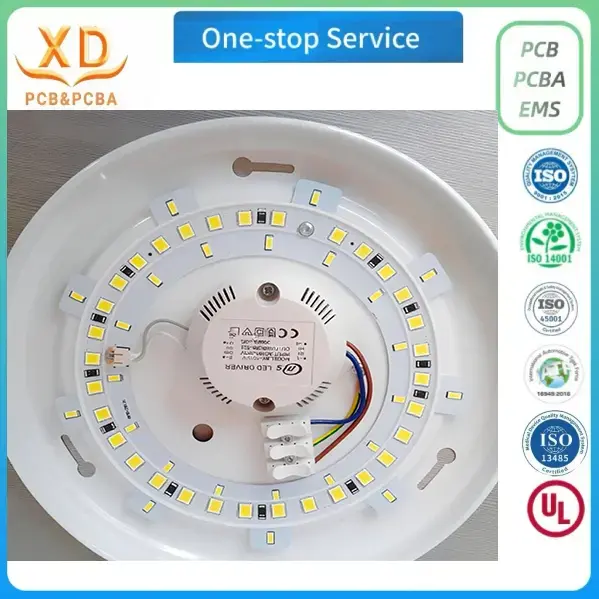
The driver's output connects to the LED board or module. Connector selection, polarity, wire routing and terminal placement must match the mechanical and electrical requirements of the lighting assembly.
Protection and control
Depending on the product, the driver may include protection against conditions such as overcurrent, overvoltage or excessive temperature. Dimming and other control functions may also be incorporated. These features must be supported by the circuit design rather than assumed to be present on every LED driver PCB.
The PCB connects the components that perform these functions. Its layout must support the required electrical paths while accounting for current levels, component placement, insulation, heat generation and manufacturing constraints.
For this reason, LED driver PCB design should begin with the circuit requirements and work toward a manufacturable board, rather than treating the PCB as a separate mechanical component.
What Is the Difference Between an LED Driver PCB and an LED Light PCB?
The LED driver PCB and the LED light PCB can be part of the same lighting product, but they perform different jobs.
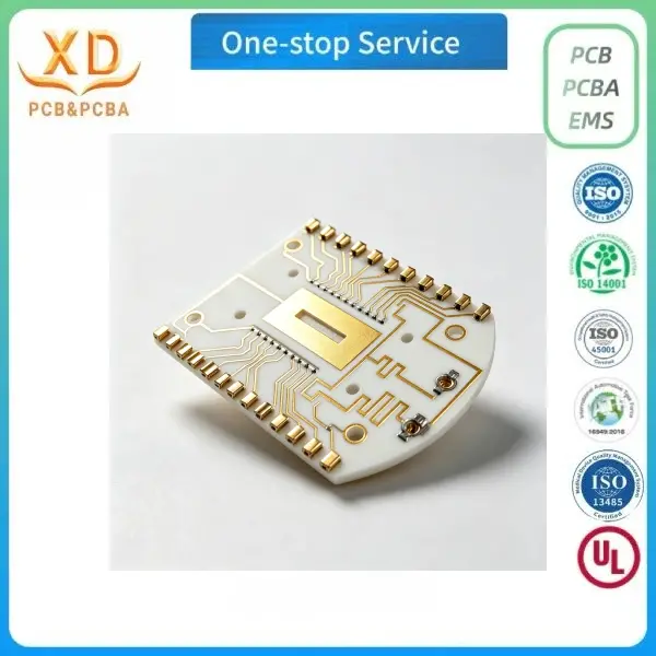
The driver board supports the electronics that condition and regulate power. The LED light board carries the LEDs that produce illumination and provides their electrical connections. Depending on the design, the LED light board may use FR-4, aluminum MCPCB or another suitable construction.
In a product with separate boards, the driver supplies the electrical output required by the LED module. The two boards must be compatible in terms of output current, voltage range, connector arrangement and mechanical integration.
For example, an LED downlight may have a driver positioned in a separate enclosure and an LED module mounted to a metal heat-spreading structure. The driver PCB and LED board have different layouts because their components and operating functions differ.
A compact lamp may instead use an integrated design in which the driver and LED circuitry share a more closely connected physical arrangement. Whether the functions are placed on separate boards or combined depends on electrical isolation requirements, available space, thermal conditions, assembly considerations and product cost.
These configurations should not be treated as interchangeable without reviewing the complete design. Integrating circuits may reduce the number of separate assemblies, but it can also change the routing, spacing, thermal and serviceability requirements.
A product manager should therefore establish the electrical architecture before finalizing the PCB specification. The key question is not simply which board material to use, but how each circuit section contributes to the operation of the finished lighting product.
Why Does LED Driver PCB Design Matter?
A driver circuit can be electrically correct in principle and still encounter problems when transferred to a physical PCB. The board layout determines how components are connected, how much space they occupy and how the circuit interacts with the enclosure and assembly process.
One important consideration is current routing. High-current paths may require different trace dimensions from low-current signal connections. The appropriate copper width depends on factors such as current, allowable temperature rise, copper thickness, trace geometry and the surrounding thermal environment. A universal trace-width value cannot replace a design-specific calculation.
Switching power supplies introduce additional layout concerns. High-frequency current loops, switching nodes and sensitive feedback signals may need careful placement and routing. Poor layout choices can contribute to electromagnetic interference, unwanted coupling or unstable circuit behavior.
Component spacing also matters. The board must provide adequate clearance for component bodies, terminals, connectors and assembly equipment. Where the circuit includes hazardous voltages, insulation distances and other safety-related requirements must be established according to the applicable standards and product design.
Mechanical integration should be considered at the same time. A driver PCB may need mounting holes, connector access, slots or specific edge dimensions to fit within the housing. The board outline should be reviewed against the actual enclosure rather than developed independently.
Manufacturability is another key part of the design process. Components should be positioned in a way that supports the intended assembly method. Fine-pitch components, closely spaced pads, unusual board outlines and restricted access can affect production planning and inspection.
From a product manager's perspective, these issues are connected. A change to the component layout may affect the board dimensions, manufacturing data, enclosure design and assembly sequence. Reviewing the complete design before fabrication helps identify conflicts while they are still relatively easy to correct.
Which Material Is Suitable for an LED Driver PCB?
Material selection depends on the circuit's electrical, thermal and mechanical requirements. The most appropriate material is the one that meets the design specification and can be manufactured consistently for the intended application.
FR-4 is a glass-fiber-reinforced epoxy laminate commonly used for electronic circuit boards. It supports a wide range of conventional electronic designs and is available in different thicknesses and material grades.
For an LED driver PCB, FR-4 may be suitable when its electrical properties, thermal limits, insulation characteristics and mechanical strength meet the requirements of the circuit. The final selection still needs to account for working voltage, component heat generation, required creepage and clearance distances, and the operating environment.
An aluminum metal-core PCB has a different construction. It typically includes a conductive copper circuit layer, an electrically insulating dielectric layer and an aluminum base. The aluminum base provides mechanical support and forms part of the thermal path from the circuit layer toward the board's mounting structure.
Aluminum MCPCBs are frequently used for LED light-source modules where heat transfer is an important design consideration. They are not automatically the preferred choice for every driver circuit, however. The material must be evaluated against the circuit's insulation requirements, component arrangement, electrical design and thermal conditions.
In some lighting products, an FR-4 driver PCB and an aluminum LED board work together. This arrangement allows each board to serve a different function within the overall system.
Xinda PCB lists FR-4 for its LED driver PCB board and aluminum substrate for its MCPCB offering. This provides a basis for discussing both board types within an LED lighting project, but the final construction should be confirmed for the specific design.
When developing a custom LED PCB, buyers should avoid choosing a material based solely on its name or price. The board specification should follow the requirements of the circuit and the complete lighting product.
How Should Copper Thickness and Board Thickness Be Specified?
Copper thickness and finished board thickness are two separate specifications. Both should be defined clearly in the fabrication documents because they affect different aspects of the board.
Copper thickness describes the conductive copper layer. It influences the current-carrying capacity of the circuit, although actual performance also depends on trace width, current distribution, thermal conditions and acceptable temperature rise.
Finished board thickness refers to the overall thickness of the completed PCB structure. It affects mechanical fit, available space, mounting arrangements and compatibility with the enclosure.
For its featured custom LED driver and aluminum PCB product, Xinda PCB lists a board thickness of 1.0–2.5 mm and copper thickness of 1–2 oz. The general aluminum PCB processing specifications provide a broader range of 0.4–3.0 mm finished thickness and 1–6 oz copper thickness.
These figures should be interpreted according to the specific product construction. The general aluminum PCB processing range does not automatically apply to every FR-4 driver board or every possible combination of material and thickness.
When preparing a quotation request, the engineering team should state the required finished thickness and copper specification rather than asking for a generic standard board. If the design is still under development, the PCB manufacturer can review the proposed requirements and confirm whether they fit the available production range.
The same principle applies to trace width and spacing. Xinda PCB lists a minimum trace width and line spacing of 0.15 mm in its general aluminum PCB process specifications. This is a stated processing parameter, not a universal recommendation for power-carrying traces. The actual design must meet its electrical and manufacturing requirements.
A complete specification reduces the risk of different suppliers quoting boards with different constructions. It also provides a consistent basis for sample approval and repeat orders.
What Information Is Needed for a Custom LED Driver PCB?
A custom LED driver PCB project should begin with a clear set of engineering and manufacturing documents. The required information depends on the development stage, but several items are especially useful when preparing a design for fabrication.
Electrical requirements
The design documentation should identify the intended input source, output requirements and relevant operating conditions. For the driver circuit, this may include voltage ranges, target current, load characteristics and any required control or protection functions.
These details establish the electrical context for the board layout. Without them, it is difficult to assess whether the component arrangement and conductive paths meet the intended requirements.
PCB fabrication data
Gerber files or equivalent fabrication data define the board's copper patterns and other manufacturing layers. Drill files communicate the required hole locations and sizes. A mechanical drawing should show the outline, dimensions, mounting features and relevant tolerances.
The files need to represent the same design revision. If the drawing and fabrication data conflict, the discrepancy should be resolved before production begins.
Material and stack-up information
The board specification should identify the intended material, layer structure, finished thickness and copper requirements. For a metal-core board, the relevant insulation and aluminum-base construction should also be confirmed.
Assembly information
If the project includes component assembly, the manufacturer may need a bill of materials, component placement data and assembly drawings. The buyer should confirm which assembly services are available and which materials or files must be supplied.
Order and inspection requirements
The request should state the sample quantity, expected production quantity, surface finish where applicable, testing requirements and packaging expectations. Any critical dimensions or special acceptance criteria should be documented in advance.
Providing these details helps the PCB manufacturer evaluate the request more accurately. It also allows the engineering and purchasing teams to compare quotations on a consistent basis.
For a custom LED PCB design service, early communication is especially valuable when the circuit is still being revised. Questions about missing files, material requirements or manufacturing limits are easier to resolve before the board enters production.
What Should Be Checked Before the First PCB Sample Is Approved?
A prototype sample is an opportunity to verify whether the manufactured board matches the released design and can proceed to the next development stage. The evaluation should be based on documented requirements rather than appearance alone.
Start with the mechanical dimensions. Check the board outline, mounting holes, slots and connector positions against the approved drawing. If the PCB needs to fit into a specific housing, a physical fit check can reveal interference that may not be apparent in the design software.
Next, review the material and thickness requirements. Confirm that the sample follows the agreed specification and that the board's surface condition is acceptable for the intended assembly.
The circuit pattern should also be reviewed. Optical inspection can help identify visible defects, while electrical testing can check relevant continuity and isolation requirements. These tests address particular aspects of PCB quality; they do not replace functional testing of the complete LED driver.
For an assembled driver, further checks may be required to verify component placement, electrical connections and circuit operation. The exact evaluation depends on the project requirements and the assembly services included in the order.
If the sample reveals a problem, record the required change and update the relevant design documents. The manufacturer should receive the approved revision before producing another sample or moving to volume production.
Sample approval is a formal decision point. Once the buyer accepts the board, the approved files and specification should be retained as the reference for subsequent manufacturing orders.
How Does PCB Manufacturing Affect LED Driver Product Development?
Manufacturing requirements should be considered during design rather than after the circuit has been completed. A layout that works in an engineering prototype may still need adjustment before it can be produced consistently.
For example, component spacing may affect soldering access and inspection. A board outline with unusual cutouts may require additional review. A copper pattern that approaches the manufacturer's minimum trace or spacing limits may require confirmation before release.
The production process also depends on the board construction. Material preparation, circuit imaging, etching, solder mask application and surface finishing must follow the requirements of the selected PCB type. Inspection methods should be appropriate to the board design and the specified acceptance criteria.
Xinda PCB lists incoming material inspection, cutting, imaging, etching, solder mask printing, AOI inspection, electrical testing, final quality assurance and packaging among its aluminum PCB manufacturing operations. The specific process and applicable checks for an LED driver PCB should be confirmed against its material construction and order requirements.
For a product manager, manufacturing review is not simply a final quality step. It connects the design specification with the practical requirements of production.
A change to the board thickness, copper pattern or material can affect the mechanical design, fabrication files and quotation. These changes should be reviewed as part of the product development process, with clear revision control to ensure that engineering, purchasing and manufacturing teams work from the same information.
Can an LED Driver PCB Be Customized for Different Lighting Products?
Yes. An LED driver PCB can be developed around the electrical and mechanical requirements of a specific lighting product. The degree of customization depends on the circuit design, production capabilities and information available to the manufacturer.
A compact bulb, a commercial downlight and an industrial lighting fixture may require different driver arrangements. Their power requirements, component layouts, enclosure dimensions, connector positions and operating environments can differ significantly.
Customization may involve the board outline, mounting holes, thickness, copper specification, circuit routing and other fabrication requirements. If the project includes assembly, component placement and assembly documentation may also need to be defined.
However, customization should begin with a clear product requirement. Changing the board shape or thickness does not automatically make the circuit suitable for a different operating condition. Electrical performance, component ratings, insulation and applicable product safety requirements must still be addressed by the responsible design team.
For buyers, the most effective starting point is to provide the manufacturer with the available design files, required board specifications, intended quantity and outstanding technical questions. If the design is not finalized, those details help identify which decisions must be resolved before production.
Xinda PCB accepts custom samples and volume orders for its PCB offerings. The precise material, manufacturing range and available assembly services should be confirmed when discussing a specific LED driver project.
Final Considerations for LED Driver PCB Development
An LED driver PCB is more than a mounting platform for electronic components. It is the physical implementation of a circuit that must operate within defined electrical, mechanical and manufacturing limits.
A successful design starts with the requirements of the driver and the LED load. The board layout must support the intended circuit, while material selection, copper thickness, finished thickness and mechanical dimensions need to match the product specification.
Manufacturing information is equally important. Complete fabrication files, consistent design revisions and clearly defined inspection requirements give the PCB manufacturer a reliable basis for production. Prototype evaluation then provides an opportunity to check the board before the project moves forward.
For LED lighting companies developing a new product or revising an existing design, these decisions should be addressed together rather than handled as isolated tasks. A clear specification improves communication between engineering, purchasing and manufacturing teams and provides a stronger foundation for repeat production.
Xinda PCB offers PCB options that include FR-4 LED driver boards and aluminum-substrate MCPCBs. For project-specific requirements, buyers can review the Custom LED Driver Aluminum PCB for LED Light Modulesand confirm the applicable specifications before requesting a quotation.
Label: