0755-27781532-8010; 02988446863













Sep 02, 2026
Why Aluminum PCBs Matter for LED Bulb Heat Dissipation
Oct 14
Intelligent Browse: 2
Heat management is an important consideration when developing an LED bulb. Although LEDs are more energy-efficient than many traditional light sources, they still generate heat during operation. If that heat remains concentrated around the LED package, the component may operate outside its intended temperature range. This can affect light output, color consistency and service life.
The circuit board plays a direct role in how heat moves away from the LEDs. In a compact bulb, the available space for thermal management is limited. The PCB must work with the driver, housing and mounting structure to keep operating temperatures within acceptable limits. An aluminum PCB provides a metal base that helps spread heat and transfer it toward the surrounding structure.
However, an aluminum base alone does not guarantee effective cooling. The dielectric layer, copper layout, LED placement and contact between the board and housing all influence the result. For lighting manufacturers, the key is to evaluate the entire thermal path rather than rely on a single material specification.
Why LED Bulbs Need Effective Thermal Management
An LED converts electrical energy into light, but part of that energy becomes heat. The amount depends on the LED package, drive current, electrical efficiency and operating conditions. The driver and other electronic components may also generate heat inside the bulb housing.
This creates a particular challenge for compact lighting products. The LED board may have limited surface area, while the housing leaves little room for a large heat sink or additional cooling components. Heat must therefore move through the available materials and interfaces before it can escape into the surrounding air.
Excessive temperature can affect LED performance in several ways. Light output may decrease as the junction temperature rises, and color characteristics can shift with operating conditions. High temperatures can also place additional stress on electronic components and solder joints. The actual effect depends on the components and the conditions under which the bulb operates.
For product developers, thermal management should be considered during the early design stage. Changing the PCB after the housing, optical components and driver have been finalized may require additional mechanical work. Reviewing the thermal path at the beginning gives the design team more flexibility to adjust the board structure and component layout.
How an Aluminum PCB Moves Heat Away from LEDs
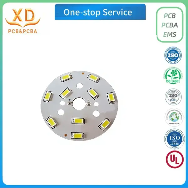
An aluminum PCB, also known as a metal-core PCB or MCPCB, typically consists of a copper circuit layer, an electrically insulating dielectric layer and an aluminum base. Each layer has a different function, and all three contribute to the performance of the board.
The copper layer forms the electrical connections and provides the mounting pads for the LED components. Heat generated at the LED package passes through the solder interface and copper pad toward the dielectric layer. From there, heat travels into the aluminum base, which spreads it across a larger area before transferring it toward the lamp housing or heat sink.
The typical thermal path can be described as:
LED package → solder interface → copper circuit layer → dielectric layer → aluminum base → mounting interface → lamp housing.
The actual path varies with the component package and mechanical construction. Heat can also move through other parts of the assembly, but the PCB-to-housing path is often an important part of the design.
The quality of this path depends on the resistance to heat flow through each layer and interface. A metal base with good heat-spreading properties cannot compensate for a poorly selected dielectric material or inadequate contact with the housing. Similarly, a well-designed PCB may still run hot if the enclosure cannot release the heat it receives.
The aluminum PCB should therefore be treated as part of the overall thermal system rather than as an independent cooling solution.
The Dielectric Layer Has a Major Role in Thermal Performance
The dielectric layer separates the copper circuit from the conductive aluminum base. This electrical insulation is essential, but the layer must also allow heat to pass through the board.
Its thermal behavior depends on the material, thickness and effective contact area. A thicker layer generally creates greater thermal resistance when other properties remain unchanged. A material with higher thermal conductivity may reduce that resistance, provided it also meets the required insulation and manufacturing specifications.
This makes the dielectric specification an important part of the PCB selection process. Two aluminum circuit boards can use the same aluminum alloy and have similar dimensions while performing differently because their insulating layers are not the same.
Product teams should confirm the dielectric construction with the manufacturer when thermal performance is a key requirement. If the design has a defined thermal resistance target, that requirement should be documented rather than left to a general material description.
Electrical isolation must remain a priority throughout the design. The dielectric layer needs to meet the applicable insulation requirements for the intended circuit. A thermal improvement is not acceptable if it compromises electrical safety or the reliability of the finished lamp.
Aluminum PCB and FR-4 PCB: Choosing the Right Construction
FR-4 is widely used for conventional electronic circuits, including many LED driver boards. Aluminum PCBs are often selected for boards that carry LEDs because their metal base provides a direct route for heat to move away from the circuit layer.
The choice depends on the function of the board and the thermal requirements of the complete product.
| Design consideration | Aluminum PCB | FR-4 PCB |
|---|---|---|
| Base construction | Aluminum base with an insulating dielectric layer | Glass-fiber-reinforced epoxy laminate |
| Thermal path | Transfers heat through the dielectric toward the metal base | Depends on the laminate, copper layout and additional thermal provisions |
| Common lighting applications | LED bulb boards, downlights and spotlights | Driver circuits and control electronics |
| Mechanical integration | Requires attention to metal-base dimensions and electrical isolation | Requires attention to laminate thickness, mounting and heat-management provisions |
| Main evaluation point | Thermal resistance of the complete board and mounting structure | Whether the board and surrounding design can meet the thermal requirements |
Neither construction is automatically suitable for every lighting product. A low-power control circuit may work well on FR-4, while an LED mounting board with a concentrated heat load may benefit from an aluminum base. Some lighting products use separate boards for the LED array and driver, allowing each board to use a construction suited to its function.
The decision should be based on operating conditions, electrical requirements, available space and cost. Changing from FR-4 to aluminum without identifying the actual source of a thermal problem may increase manufacturing cost without producing the expected improvement.
Copper Thickness and Layout Influence Heat Distribution
Copper primarily carries electrical current, but it also affects how heat spreads across the PCB. The copper thickness, trace width and layout influence conductor resistance and the distribution of heat around the LED mounting pads.
The featured custom LED bulb PCB specifies copper thickness from 1 oz to 2 oz. Xinda PCB's general aluminum PCB process specification lists a broader copper thickness range from 1 oz to 6 oz. The appropriate selection depends on the circuit current, trace geometry and manufacturing requirements.
Increasing copper thickness can reduce conductor resistance for a given trace geometry. Larger copper areas may also help distribute heat away from localized sources. However, heavier copper is not always the best option. It can make fine-feature fabrication more demanding and needs to be compatible with the required trace width and spacing.
The circuit layout should be evaluated with both electrical and thermal requirements in mind.
LED pads: The copper pads must match the selected package and provide the required soldering area.
Trace width: Conductors need to carry the expected current without excessive voltage drop or heating.
Copper distribution: The layout should provide suitable current paths and avoid unnecessary restrictions around high-load areas.
Electrical clearance: Spacing between conductors must satisfy the circuit requirements and manufacturing capabilities.
Fabrication limits: Copper thickness, trace width and line spacing should be reviewed together before the design is released.
The general process specification lists a minimum trace width and spacing of 0.15 mm. This should not be treated as a universal guarantee for every copper thickness and circuit pattern. The actual artwork needs to be checked against the selected construction.
It is also important to distinguish current-carrying capacity from overall thermal performance. A trace may meet its electrical requirements while the board still develops localized hot spots because of LED placement or a restricted thermal path. Copper weight alone cannot determine the temperature of the finished assembly.
Selecting the Aluminum Base Thickness
The aluminum base provides mechanical support and helps spread heat away from the LED mounting area. Its thickness affects rigidity, overall dimensions and the way the PCB fits against the lamp housing.
The featured LED bulb PCB is specified with a finished board thickness of 1.0–2.0 mm. The general aluminum PCB process specification lists a finished thickness range of 0.4–3.0 mm. These figures describe different specification scopes, so the required construction should be confirmed for the particular order.
Finished board thickness should not be confused with aluminum base thickness. The complete board includes the copper and dielectric layers, and its final dimensions depend on the construction. The fabrication drawing should identify the required finished thickness and relevant tolerances.
A thinner board may help when the bulb has limited internal clearance, but it still needs adequate mechanical stability. A thicker board may provide additional rigidity while increasing assembly height or affecting the mounting arrangement.
The effect on heat transfer also depends on the rest of the thermal system. Increasing aluminum thickness does not guarantee a proportional reduction in LED temperature. The dielectric layer, board area, mounting interface and heat-rejection capacity of the housing remain important.
The product team should evaluate base thickness together with the complete board structure and mounting design. Where the thermal load is demanding, testing the assembled bulb provides more useful evidence than selecting a board solely by its thickness.
LED Placement and Localized Heat Concentration
LED placement determines where heat enters the PCB and how it spreads across the copper and aluminum layers. Components concentrated in a small area can create a different thermal distribution from LEDs spread across a larger surface.
The layout must also satisfy optical and mechanical requirements. The position of each LED affects the relationship between the light sources, diffuser, reflector and other components. Moving LEDs to improve thermal distribution may change light uniformity or interfere with the existing housing design.
A thermal review should therefore consider the complete LED arrangement. The board must provide sufficient space for the packages and their solder pads, while maintaining the required electrical clearances and assembly tolerances. The distribution of heat should be considered alongside the electrical connections and optical layout.
If testing identifies a localized hot spot, the engineering team can examine the LED spacing, copper distribution and board construction. A larger PCB may not be possible when the housing dimensions are fixed, and a heavier copper layer may not resolve a problem caused by poor contact with the mounting surface.
The best solution depends on the source of the temperature difference. Thermal simulation and controlled testing can help the team identify where heat accumulates and whether a proposed design change addresses the problem.
The Lamp Housing and Mounting Interface Complete the Thermal Path
Heat does not disappear when it reaches the aluminum base. It must continue into the surrounding structure and then move from the lamp into the environment.
In many LED bulbs, the housing or an internal metal support acts as part of the heat-rejection system. The PCB may be attached directly to a metal surface or installed using a thermal interface material. The quality of this connection affects the resistance to heat flow between the board and the housing.
An uneven mounting surface can reduce contact area. An unsuitable thermal pad or adhesive may also create an additional barrier. The design should therefore account for surface flatness, mounting pressure, interface thickness and assembly tolerances.
The housing must also be capable of releasing the heat it receives. A low-resistance connection between the PCB and housing will have limited benefit if the enclosure cannot transfer that heat to the surrounding air under the intended operating conditions.
This is particularly relevant for compact bulbs with limited external surface area. The product team needs to consider the board and housing as a combined thermal structure. Changes to the enclosure, mounting arrangement or ventilation conditions may affect performance even when the PCB remains unchanged.
The complete bulb should be tested in its intended configuration whenever the objective is to verify operating temperature. Measurements from an isolated PCB cannot fully represent the thermal behavior of the finished lamp.
Thermal Requirements Across Different Lighting Applications
The thermal requirements of an LED PCB vary with the application. Residential bulbs, commercial downlights, outdoor fixtures and automotive lighting may use similar board materials, but their operating conditions and mechanical arrangements can differ significantly.
Residential and commercial lighting
LED bulbs, spotlights, downlights and ceiling lights often have limited internal space. Their PCB designs must balance heat transfer with the available mounting area, optical layout and enclosure dimensions.
An aluminum PCB can provide a practical mounting platform when the board construction and housing are designed together. The board diameter, LED distribution and contact with the surrounding structure all influence the final result.
Outdoor and industrial lighting
Outdoor and industrial products may operate under wider temperature variations or more demanding environmental conditions. The thermal design should reflect the intended operating schedule, installation position, ambient temperature and enclosure.
An aluminum base can support heat transfer, but it does not by itself establish resistance to moisture, corrosion, vibration or weather exposure. Those requirements depend on the complete product construction and the relevant environmental testing.
Automotive lighting
Automotive lighting assemblies can face restricted installation space, temperature changes and vibration. The PCB must meet the electrical and mechanical requirements of its intended vehicle application.
An aluminum PCB may help manage heat from LED components, but the complete design still requires appropriate mounting, electrical insulation and environmental validation. Material selection alone cannot establish suitability for automotive use.
Across these applications, the board should be selected according to the actual operating conditions rather than the product category alone.
Common Causes of Poor LED PCB Thermal Performance
When an LED bulb operates hotter than expected, the aluminum base is not necessarily the source of the problem. The full thermal path should be reviewed before changing the PCB specification.
| Potential issue | Possible effect | What to review |
|---|---|---|
| Dielectric layer with unsuitable thermal properties | Greater resistance between the circuit and aluminum base | Confirm the dielectric specification and board construction |
| Poor contact between PCB and housing | Restricted heat transfer into the enclosure | Check surface flatness, mounting pressure and interface material |
| Concentrated LED placement | Uneven temperature distribution | Review component spacing and copper layout |
| Limited heat rejection from the housing | Heat accumulates after leaving the PCB | Evaluate the housing under actual operating conditions |
| Incorrect drive current | Higher heat generation than expected | Verify driver output and LED operating conditions |
| Incomplete thermal validation | Problems remain undetected before production | Test the complete bulb under defined conditions |
The order of investigation matters. Increasing board thickness may raise cost without addressing excessive drive current or inadequate contact with the housing. A structured review helps identify the part of the system that requires attention.
When a design change is made, the original and revised assemblies should be evaluated under the same conditions. This allows the team to determine whether the change improved the intended thermal parameter rather than relying on assumptions about the material.
Validating Thermal Performance Before Production
Thermal validation should begin with a defined test plan. The test conditions need to specify the LED configuration, drive current, input conditions, bulb orientation, enclosure, ambient temperature and measurement locations.
The PCB should first be checked against its approved specification. Material, finished thickness, copper requirements, dimensions and mounting features should all match the design. The assembled board should then be inspected for component placement, solder quality and mechanical fit.
The complete bulb can be operated under controlled conditions to measure temperatures at specified locations. The test should allow the assembly to approach thermal stability according to the agreed procedure, and the operating conditions should be recorded so the results can be reproduced.
Where junction temperature is a critical parameter, a surface temperature reading alone may not be sufficient. The appropriate measurement or estimation method should follow the LED manufacturer's guidance and the project's validation requirements.
The results should be checked against the specified limits for the LEDs, driver and finished product. If the assembly does not meet its requirements, the engineering team should investigate the thermal path before deciding whether to change the board material, dielectric layer, copper layout or mounting structure.
Relevant tests should be repeated after significant design changes. This provides evidence that the revised construction meets the product's requirements before volume production begins.
Choosing an Aluminum PCB Manufacturer
A suitable manufacturer needs to produce the required board construction consistently and confirm whether the actual design fits its process capabilities. A general list of available materials and thicknesses is useful, but it does not replace a review of the fabrication files.
For an LED bulb PCB project, the buyer should confirm the aluminum alloy, finished thickness, copper specification, dielectric requirements and surface finish. Trace dimensions and board outline tolerances should also be checked against the intended design.
If assembled boards are required, the quotation should clarify whether SMD placement, component sourcing, soldering, inspection and additional testing are included. These services have different requirements from bare-board fabrication and should not be assumed from the product name alone.
The buyer should also ask how the supplier handles samples, production revisions and repeat orders. Consistent documentation helps ensure that the approved sample and later production batches use the same specifications.
The most useful supplier review focuses on the requirements that affect the finished bulb. This includes the thermal construction, mechanical fit, electrical isolation, inspection scope and any testing needed to confirm performance.
Custom Aluminum LED Bulb PCBs from Xinda PCB
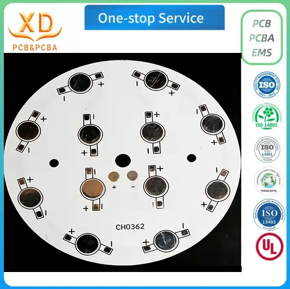
Xinda PCB offers custom aluminum PCB manufacturing for LED lighting applications. Its featured LED bulb circuit board uses 5052 aluminum alloy and specifies a finished board thickness of 1.0–2.0 mm with copper thickness of 1–2 oz. These specifications provide a starting point for projects that need a custom metal-core board for an LED lamp.
The company's general aluminum PCB process specification lists a broader finished-board thickness range of 0.4–3.0 mm and copper options from 1 oz to 6 oz. Available surface finishes include OSP, HASL, immersion gold, immersion tin and immersion silver. The final construction and tolerances should be confirmed against the project drawing.
The published manufacturing workflow includes incoming material inspection, cutting, imaging, etching, solder mask printing, AOI inspection, electrical testing, final quality inspection and packaging. Custom samples and volume orders are accepted. Projects that require SMD assembly or additional thermal validation should confirm the relevant service scope with the company before placing an order.
A quotation request should include the PCB drawing, target quantity, material and thickness requirements, copper specification, surface finish and any known thermal or electrical requirements. If the design remains under development, the buyer should identify the parameters that still need engineering review.
A clear specification allows the manufacturer to assess production feasibility and helps the buyer compare quotations on a consistent basis. It also creates a reliable starting point for sample evaluation and subsequent production.
Aluminum PCBs provide a useful thermal path for many LED bulb designs, but their performance depends on more than the metal base. The dielectric layer, copper layout, LED placement, mounting interface and housing all influence how heat moves through the finished product.
A reliable thermal design starts with the actual operating conditions and considers the complete path from the LED junction to the surrounding environment. Board thickness and copper weight should be selected according to the design requirements rather than treated as independent measures of cooling performance.
For lighting manufacturers, a clear PCB specification and a controlled sample-validation process provide a sound basis for production decisions. By evaluating the complete assembly and confirming the required manufacturing details, product teams can select an aluminum LED bulb circuit board that better fits the electrical, thermal and mechanical demands of the finished lamp.
Label: