0755-27781532-8010; 02988446863















Jun 10, 2026
Custom Circular LED Aluminum PCB Manufacturing: Materials, Specifications and Quality Checks
Oct 19
Intelligent Browse: 1
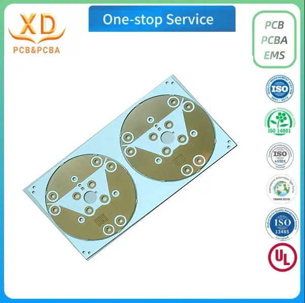
A custom circular LED aluminum PCB may look like a simple round metal-core circuit board, but getting it ready for production requires more than defining its diameter and copper thickness. The board must follow the design files accurately, fit the intended lighting assembly, and meet the electrical and mechanical requirements established before fabrication begins. Even small differences in the outline, mounting holes or component layout can create problems when the PCB is installed in a finished luminaire.
For LED lighting manufacturers, the manufacturing process also affects purchasing decisions. A prototype may be acceptable for testing, but repeat orders need consistent dimensions, material specifications and surface quality. If these details are not clearly documented, production batches can differ from the approved sample or require unnecessary adjustments during assembly.
Custom circular LED aluminum PCB manufacturing involves several connected decisions, from reviewing the original design files to checking the finished boards before shipment. Knowing what information to provide, which specifications to confirm and what quality records to request helps buyers communicate more effectively with a PCB manufacturer and reduces avoidable delays.
What Makes Custom Circular LED PCB Production Different?
Circular PCBs have a different mechanical profile from conventional rectangular boards. Their outlines often follow the shape of a lamp housing, reflector, heat-spreading structure or mounting plate. Some designs have a simple round edge, while others include cutouts, screw holes, notches or sections removed to accommodate internal components.
These features need to be considered alongside the electrical layout. A board can match the nominal diameter on a drawing and still fail to fit if the mounting holes are misplaced or the edge clearance is insufficient. For lighting products manufactured in volume, a small dimensional mismatch can affect the assembly of an entire batch.
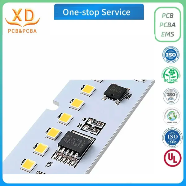
Aluminum PCBs introduce another set of considerations. Unlike a conventional FR-4 board, an aluminum metal-core PCB generally contains a conductive circuit layer, an electrically insulating dielectric layer and an aluminum base. The dielectric separates the circuit from the metal base while providing a thermal path between them. The specific construction and material properties depend on the board design and the selected material system.
For circular LED boards, the manufacturer must therefore work with both the circuit pattern and the mechanical outline. The production files should define the copper artwork, board perimeter, holes and other relevant features. Material specifications and thickness requirements also need to be confirmed before fabrication.
The aim is not simply to produce a board that looks round. It is to manufacture a circuit board that follows the approved design and can be incorporated into the intended lighting product without unexpected changes.
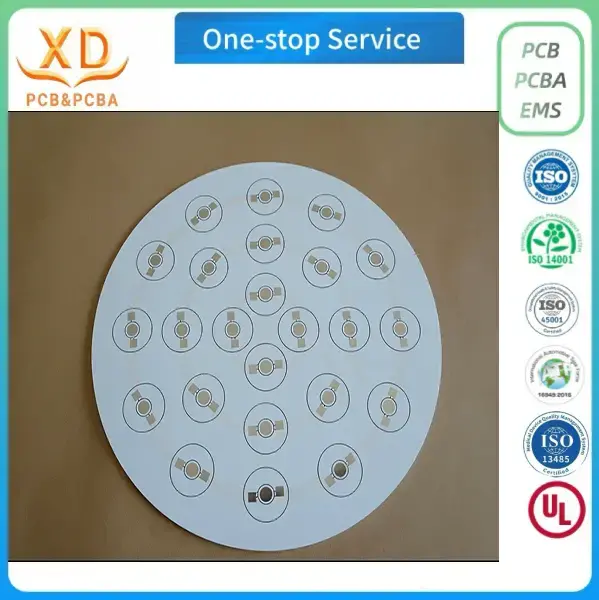
Material Selection and the Aluminum Base
Material selection should begin with the requirements of the finished lighting product. Buyers need to consider the intended operating environment, board dimensions, mounting method, electrical design and thermal requirements before confirming the material specification.
The aluminum base is an important part of the construction. It provides mechanical support and serves as part of the thermal path beneath the circuit layer. Its thickness and properties can influence the board's rigidity, weight and ability to fit within the available housing.
Xinda PCB lists 5052 aluminum alloy for its featured custom circular LED aluminum PCB. The featured product specifies a finished board thickness of 1.0–2.5 mm and copper thickness of 1–2 oz. These are useful reference specifications for buyers considering this product, but the actual production requirements should be confirmed against the approved design.
The general aluminum PCB processing range is broader than the featured product specification. Depending on the applicable board construction and manufacturing requirements, the listed general range includes finished board thicknesses of 0.4–3.0 mm and copper thicknesses of 1–6 oz. These general capabilities should not be interpreted as meaning that every combination is available for every circular board design.
Specification | Featured circular LED aluminum PCB | General aluminum PCB processing range |
Aluminum material | 5052 aluminum alloy | Confirm the material for the specific order |
Finished board thickness | 1.0–2.5 mm | 0.4–3.0 mm |
Copper thickness | 1–2 oz | 1–6 oz |
Minimum trace width | Confirm against the design | 0.15 mm |
Minimum line spacing | Confirm against the design | 0.15 mm |
Maximum processing size | Confirm the specific board and tooling requirements | 120 cm × 60 cm |
These figures are reference specifications, not a substitute for a production review. Buyers should confirm the required stack-up, copper weight, insulation structure and mechanical dimensions before placing an order.
It is also worth distinguishing copper thickness from finished board thickness. Copper weight describes the copper layer, while finished thickness refers to the completed board structure. The two values affect different parts of the design and should be recorded separately in the manufacturing documents.
If a lighting product is being redesigned, material changes should be reviewed rather than assumed to be interchangeable. A different aluminum base or dielectric construction may affect the board's mechanical characteristics and thermal behavior. The manufacturer should evaluate whether the revised specification is suitable for the existing layout and production requirements.
Preparing Design Files for Fabrication
A clear set of design files gives the PCB manufacturer a reliable basis for production. Incomplete or conflicting documentation can lead to questions about the board outline, copper pattern, hole positions or finished dimensions. Resolving those questions after production has started is usually more disruptive than confirming the details beforehand.
For a custom circular LED aluminum PCB, the design package should contain the information needed to reproduce the intended board. The exact file set depends on the design and the manufacturer's requirements, but the following items are commonly relevant:
● Gerber files or equivalent fabrication data: These define the copper artwork and other manufacturing layers required for the board.
● Drill data: This identifies the locations and sizes of holes that need to be drilled.
● Mechanical drawing: This communicates the outside diameter, cutouts, mounting holes, critical dimensions and applicable tolerances.
● Layer and material information: This records the intended board construction, including the copper and insulation requirements.
● Fabrication notes: These clarify surface finish, special requirements, reference dimensions and any features that may not be obvious from the artwork alone.
The files should describe the same version of the board. For example, if the mechanical drawing shows a revised mounting-hole position but the fabrication data still contains the earlier position, the manufacturer needs to identify and resolve the discrepancy before proceeding.
Revision control matters when several departments are involved. An engineering team may revise the LED arrangement while the purchasing team continues using an older quotation drawing. A simple revision identifier and approval date can help both parties confirm which version is authorized for production.
Buyers should also identify which dimensions are critical to assembly. The outside diameter may need to fit tightly inside a lamp housing, while other dimensions may have more flexibility. Highlighting these differences helps the manufacturer focus on the requirements that matter most to the finished product.
If the board includes unusual cutouts, closely spaced holes or a narrow edge section, these features should be shown clearly in the drawing. Where the design has tight tolerances, the buyer should ask the manufacturer to confirm feasibility rather than assume that every dimension can be produced without adjustment.
Turning the Design Into a Manufacturing Plan
Once the files are available, the manufacturer needs to review them before production. This review connects the design intent with the practical requirements of board fabrication.
The first task is to confirm that the material, board thickness, copper specification and outline are compatible with the requested construction. The manufacturer can then check whether the artwork contains enough information for the required layers and whether any dimensions or notes conflict with one another.
Production planning also needs to account for the quantity ordered. Prototype orders and volume orders may use the same basic design, but they have different priorities. A prototype run is often intended to verify the mechanical fit or support an initial electrical evaluation. A volume order places greater emphasis on repeatability, consistent inspection and the management of approved production records.
For circular boards, the outline deserves particular attention during this review. A nominal diameter alone may not describe all the mechanical requirements. Mounting holes, notches and cutouts can determine how the board is positioned inside the final product. These features should be checked against the drawing before the design is released.
The manufacturer should also clarify any unresolved technical questions with the buyer. If a required dimension is missing, it is better to obtain written confirmation than to make an assumption that could affect the finished board.
This stage is an opportunity to settle practical details such as material availability, surface finish, sample quantity, expected production quantity and packaging requirements. It also gives both parties a shared record of the specifications that will be used to assess the finished order.
How the PCB Fabrication Process Is Controlled
Aluminum PCB fabrication involves several stages, and each stage has a different purpose. The exact production method depends on the board design, but material verification, circuit pattern formation, solder mask application and final inspection all contribute to the finished result.
Incoming material inspection is an early checkpoint. The manufacturer checks the supplied material against the order requirements before it enters production. If the material type or thickness does not match the approved specification, the discrepancy should be resolved before further processing.
The material is then prepared to the required size. During circuit imaging, the intended copper pattern is transferred to the working material. Etching removes unwanted copper to create the circuit features defined by the artwork. The result depends on the accuracy of the supplied design data and the control of the fabrication process.
Solder mask printing follows where required by the board design. The solder mask provides coverage over designated areas of the circuit while leaving the necessary exposed regions available. Its placement and appearance should be checked against the approved artwork and manufacturing requirements.
Surface treatment is another important part of the process. The selected finish should be confirmed before production because it affects the exposed copper surfaces and their suitability for the intended assembly and storage conditions.
Inspection takes place at appropriate points in production rather than relying only on a visual check at the end. Automated optical inspection, where applicable, can help identify visible circuit-pattern defects. Electrical testing checks the relevant electrical continuity and isolation requirements supported by the test method. Final quality assurance reviews the completed boards before packaging.
Each checkpoint addresses a different type of issue. A visually acceptable board is not automatically electrically correct, and an electrically functional board may still have a mechanical defect that prevents installation. The inspection plan should therefore reflect the requirements established for the particular order.
For buyers, the important question is not simply whether the supplier has a production process. It is whether the process and inspection arrangements are appropriate for the board being ordered.
Surface Finish and Exposed Copper
Surface finish should be specified before fabrication begins. The correct choice depends on the design, the exposed copper areas and the requirements of the finished lighting product.
Xinda PCB lists several surface-treatment options for its general aluminum PCB processing: OSP, hot air solder leveling (HASL), immersion gold, lead-free immersion tin and immersion silver. Availability for a particular custom circular board should be confirmed during quotation and engineering review.
These finishes should not be treated as interchangeable options without considering the application. Their characteristics, processing requirements and suitability for particular assembly conditions differ. The choice should follow the intended use of the board and the requirements of the relevant manufacturing process.
OSP is an organic surface preservative applied to exposed copper. For Xinda PCB's general processing specifications, the listed OSP thickness is 0.20–0.40 μm. This is a reference specification for that finish and should be confirmed for the actual order where applicable.
When comparing quotations, buyers should ensure that the quoted surface finish matches the approved requirement. If one supplier quotes a different finish from another, the prices may not represent equivalent products.
The same principle applies when an existing design is transferred to a new manufacturer. The finish used for the original board should be documented rather than inferred from photographs or assumed from a previous purchase order. A change should be reviewed and approved before it becomes part of the production specification.
Quality Checks That Matter for Circular Aluminum PCBs
Quality inspection should be connected to the drawing and the intended use of the finished board. A generic statement that a product has been inspected provides limited information unless the buyer understands what was checked.
For circular LED aluminum PCBs, several areas deserve attention.
Mechanical dimensions
The outside diameter, mounting-hole positions and specified cutouts should be checked against the approved drawing. These dimensions affect whether the board can be installed in its intended housing. Where tolerances are specified, inspection should use the approved limits rather than an informal visual judgment.
Circuit pattern
The copper artwork should be consistent with the released fabrication data. Optical inspection can help identify visible defects such as unwanted copper remnants, missing pattern areas or other irregularities. The inspection criteria should be appropriate to the board's design and manufacturing requirements.
Electrical condition
Electrical testing can identify certain open circuits and unintended connections, depending on the test setup and coverage. Buyers should confirm the test requirements for the order if specific electrical verification is important to their application. A continuity or isolation test does not replace the functional evaluation of the complete LED lighting product.
Surface condition
The board should be checked for visible damage, contamination and defects that could affect installation or the specified surface finish. Inspection criteria should distinguish between cosmetic conditions and defects that affect function or fit.
Material and thickness
The supplied material and finished board thickness should be consistent with the approved specification. These checks are particularly important when the design relies on a specific fit within a lamp housing or requires a defined board construction.
Packaging condition
Finished boards should be packed in a way that protects them during handling and transportation. Packaging requirements may vary according to board size, order quantity and the buyer's receiving procedures.
No single check covers every potential problem. Mechanical inspection, optical inspection, electrical testing and material verification address different requirements. Buyers should therefore establish acceptance criteria that reflect the design rather than relying on a single pass-or-fail statement.
For recurring orders, keeping a record of the approved specification and inspection requirements also makes it easier to compare later batches with the original order.
Prototype Samples and Approval Before Volume Production
A prototype is useful because it allows the buyer to evaluate a physical board before committing to a larger quantity. However, the value of a sample depends on how it is reviewed.
The first step is to compare the received board with the approved mechanical drawing. The outside diameter, mounting holes, cutouts and overall thickness should be checked against the dimensions that matter to the assembly. If the board is intended to sit inside a lamp housing, a physical fit check can reveal issues that may not be obvious from the electronic files alone.
The circuit pattern and surface finish should also be reviewed. If electrical testing is part of the sample evaluation, the test results should be considered alongside the design requirements. Where the board will be used in a complete lighting product, the relevant system-level evaluation remains the responsibility of the product development process.
Any differences should be documented before the sample is approved. If the board needs a revised outline or a change to the fabrication data, the updated files should receive a new revision identifier. Otherwise, the manufacturer may have difficulty distinguishing the approved version from the earlier sample.
Once the sample is accepted, the buyer should retain the approved drawing, specification and relevant inspection records. These documents provide a reference for volume orders and help prevent unapproved changes from entering production.
Sample approval should not be treated as a formality. It is the point at which the buyer confirms that the manufactured board matches the agreed requirements closely enough to proceed with the next stage of the project.
Managing Repeat Orders and Production Consistency
The requirements for a repeat order should be based on the approved product specification rather than a general description such as “same as last time.” This is especially important when a supplier handles multiple circular PCB designs with similar diameters or board thicknesses.
A complete order record should identify the product, drawing revision, material, copper thickness, finished board thickness, surface finish, quantity and any special inspection or packaging requirements. If a specification changes, the change should be communicated and approved before the next production run.
Buyers should also clarify whether a new order uses the same approved files and material requirements as the previous batch. A design revision, material substitution or surface-finish change may affect how the board compares with the approved sample.
For larger orders, delivery planning and quantity confirmation are also important. The purchasing team should establish the required quantity and delivery schedule with the supplier before production. If the order is split into multiple shipments, both parties should agree on the applicable documentation and acceptance requirements.
Packaging and identification help maintain order control after the boards leave the factory. Clear labels can make it easier for the receiving team to distinguish different designs, revisions or batches. The specific labeling format should be agreed upon when the buyer has internal traceability requirements.
Repeatability does not depend on a single manufacturing step. It comes from maintaining a clear specification, using the correct design revision, applying suitable process controls and checking the finished product against agreed acceptance criteria.
Choosing a Manufacturer for a Custom Circular LED Aluminum PCB
Price matters, but the lowest quotation is not necessarily the most suitable choice for a custom board. A meaningful comparison should consider whether the supplier can meet the specified material, dimensions, circuit requirements, surface finish and quality expectations.
Buyers can begin by asking the manufacturer to confirm the required board construction and production range. If the design calls for a particular thickness or copper weight, the quotation should state that specification clearly. General capability statements should not replace confirmation of the actual product requirements.
The manufacturer's design-review process is another useful point of comparison. A supplier should be able to identify missing information or conflicting dimensions before production starts. Clear communication at this stage can prevent avoidable revisions and make the quotation more accurate.
Inspection arrangements should also be discussed. Buyers should understand whether the order includes dimensional checks, optical inspection and electrical testing as applicable. If particular measurements or inspection records are required, these should be agreed upon before the purchase order is issued.
The sample process can provide further evidence of how the supplier handles custom work. A well-managed sample order should follow a defined specification and provide a clear basis for approval. For recurring production, the supplier should also be able to work from the approved files and communicate when a requested change affects the existing requirements.
Finally, compare quotations on an equivalent basis. Board material, finished thickness, copper weight, surface finish, quantity, testing requirements and packaging can all affect the quoted price. If these details differ between suppliers, a direct price comparison may be misleading.
A manufacturer that provides clear technical communication and a documented production specification gives buyers a more reliable basis for evaluating the order.
Custom Circular LED Aluminum PCB Solutions From Xinda PCB
Xinda PCB provides aluminum PCB manufacturing for lighting applications, including custom circular LED aluminum PCBs used in downlights and panel lights. Its featured circular product uses 5052 aluminum alloy, with a listed finished board thickness of 1.0–2.5 mm and copper thickness of 1–2 oz.
The broader aluminum PCB processing range includes finished board thicknesses of 0.4–3.0 mm, copper thicknesses of 1–6 oz, and a listed minimum trace width and line spacing of 0.15 mm. The actual requirements for each design should be reviewed and confirmed before production.
The manufacturing process includes incoming material inspection, cutting, circuit imaging, etching, solder mask printing, AOI inspection, electrical testing, final quality assurance and packaging. Custom samples and volume orders are accepted, allowing buyers to discuss their requirements before moving to larger production quantities.
When requesting a quotation, it is helpful to provide the board's fabrication files, mechanical drawing, required material, finished thickness, copper thickness, surface finish and order quantity. Any critical dimensional tolerances or special inspection requirements should also be included.
For product details and quotation requests, visit Xinda PCB or contact the team at bluesky@xdpcba.com or Sales10@xdpcba.com.
Final Considerations Before Placing an Order
Successful custom circular LED aluminum PCB production begins with a clear specification. The material, circuit artwork, board outline, mounting features and surface finish need to describe the same approved design. Manufacturing and inspection requirements should then be matched to the intended application.
Before ordering, buyers should check that the fabrication files are complete, the critical dimensions are defined, and the quoted specifications match the requested product. A prototype should be reviewed against those requirements, and any revisions should be documented before volume production begins.
For repeat orders, retaining the approved design files and acceptance criteria helps maintain consistency between batches. These steps provide a practical foundation for working with a PCB manufacturer and keeping custom LED lighting projects on schedule.
Label: