0755-27781532-8010; 02988446863















Sep 11, 2026
How to Design a Custom LED Controller PCB for CCTV IR Ring Light Modules
Nov 02
Intelligent Browse: 0
A reliable LED controller PCB is an important part of a CCTV infrared ring light module. It supports the electrical connection and control of the LED array, while the board structure also affects heat transfer, component placement, assembly, and long-term operating stability. For camera manufacturers and security equipment suppliers, choosing the right circuit board involves more than arranging LEDs in a circular pattern. The design must account for the LED electrical requirements, available space around the camera lens, thermal conditions, power input, and the way the lighting module will be assembled into the finished product.
An aluminum substrate PCB is worth considering when the LED array produces enough heat to make thermal management a major design concern. Its metal base provides a heat-spreading path through an electrically insulating dielectric layer. Depending on the circuit architecture, the LED board can be manufactured as an aluminum metal-core PCB, while the more complex control or driver circuit can be placed on a separate FR-4 board. This arrangement is particularly relevant to CCTV IR ring light modules, where the circular LED board and the control electronics may have different layout and thermal requirements.
For buyers comparing led pcb aluminium options, the key is to match the board construction to the actual LED load and mechanical design. This article explains the main design decisions, from circuit architecture and thermal planning to PCB fabrication, PCBA assembly, and supplier evaluation.
The Role of a Controller PCB in a CCTV IR Ring Light
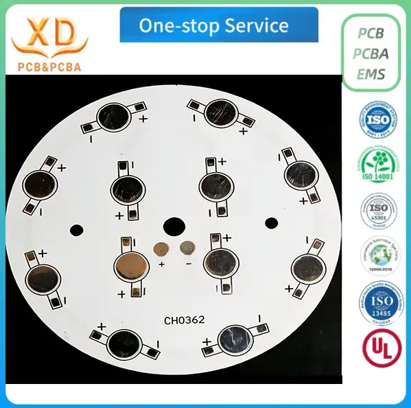
A CCTV infrared lighting module is designed to provide additional illumination for a camera in low-light or dark environments. Its LED array is commonly arranged around or near the camera lens. The ring-shaped layout helps distribute light around the optical opening, while the supporting electronics provide the electrical connections and control functions required by the module.
The LED controller PCB may perform several roles, depending on the product architecture:
Providing electrical connections between the power input, LED array, and driver circuit.
Supporting current regulation through the selected driver topology.
Distributing power across the LED branches.
Providing connection points for the camera or lighting system.
Supporting the mechanical arrangement of LEDs, connectors, and mounting features.
The exact functions depend on the design. Some products place the LED driver components directly on the LED board. Others use a separate driver PCB connected to the circular aluminum board. The second arrangement can make the LED layout more focused on thermal management, while the driver board accommodates additional control components and routing.
This distinction matters when preparing a quotation. A supplier needs to know whether the requirement is for a bare aluminum LED board, a fully assembled LED PCBA, a separate driver board, or a complete set of interconnected boards. These are different manufacturing scopes and may require different materials, processes, and inspection steps.
For CCTV equipment manufacturers, the board should also fit the camera housing and lens assembly. A technically suitable circuit board may still be unsuitable if its inner opening, outer diameter, mounting holes, or connector position do not match the mechanical structure.
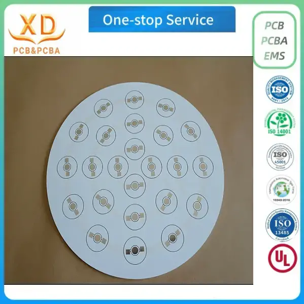
Why Aluminum Substrate PCB Is Used for LED Modules
LEDs convert electrical energy into light, but part of the input energy is also released as heat. When multiple LEDs operate on a compact circular board, heat can accumulate around the LED packages and nearby components. The thermal path therefore needs to be considered during the early design stage.
An aluminum substrate PCB typically consists of a conductive copper circuit layer, an electrically insulating dielectric layer, and an aluminum base. The aluminum base helps spread heat away from the LED mounting area. The dielectric layer provides electrical isolation between the copper circuit and the metal base while also contributing to the board's thermal performance.
This structure is commonly used for LED lighting products where heat dissipation is an important design requirement. For a CCTV infrared ring light, the board may operate inside a relatively compact camera assembly, so the available space for heat spreading and airflow can be limited.
The main design considerations include:
Heat spreading: The aluminum base helps distribute heat across a wider area instead of concentrating it only around individual LED packages.
Mechanical support: The metal base provides a rigid structure for a circular or custom-shaped LED board.
Compact assembly: A metal-core board can combine the LED circuit and thermal base in one board structure.
Product integration: The board outline can be designed around the camera lens, housing, and mounting points.
Aluminum PCB should not be selected only because the product contains LEDs. The actual LED power, operating current, board dimensions, dielectric properties, thermal interface, and enclosure design all influence the result. A lower-power indicator board may not need the same construction as a high-output infrared illuminator.
The goal is to select a board structure that meets the thermal and electrical requirements without adding unnecessary cost or complexity.
Choosing Between an Integrated LED Board and a Separate Driver PCB
One of the first decisions in a custom LED module project is whether to place the LED array and driver circuit on the same board.
An integrated design places the LEDs and relevant driver components on one PCB. This can reduce the number of separate boards and interconnections. It may also simplify the mechanical assembly when the circuit is relatively straightforward and the available layout area is sufficient.
However, the LED array and driver circuit do not always have the same design priorities. The LED section may require a metal-core construction for heat spreading, while the control section may need more complex routing, additional signal connections, or components that are better accommodated on FR-4.
A split-board architecture uses an aluminum LED board and a separate driver PCB. The aluminum board carries the LED packages and their electrical connections. The driver board handles the relevant power-control and supporting electronic functions. The two boards are connected through wires, connectors, or another suitable interconnection method.
| Design factor | Integrated LED and driver board | Separate LED and driver boards |
|---|---|---|
| Board arrangement | One combined circuit board | Aluminum LED board plus driver PCB |
| Layout priorities | LED thermal and driver routing share one design | LED and driver layouts can be optimized separately |
| Interconnection | Fewer board-to-board connections | Requires a suitable electrical connection |
| Mechanical integration | Depends on available board area | Allows more flexibility in board placement |
| Design suitability | Relatively compact or straightforward circuits | Designs with different thermal and routing needs |
Neither approach is automatically better. The choice depends on the power architecture, LED count, driver requirements, available enclosure space, and assembly process.
For a CCTV IR ring light, a separate driver PCB may be useful when the circular LED board has limited space or when the driver components would make the LED layout difficult to optimize. The project team should define the connection method and board locations before finalizing the mechanical drawings.
Key LED Controller PCB Design Considerations
A functional LED board starts with an electrical design that matches the selected LED components. The board layout should not be finalized before the electrical requirements and operating conditions are clear.
LED current and driver selection
LEDs require an appropriate drive method. The current regulation approach should be selected according to the LED specifications, input voltage range, number of LEDs, and required operating modes. A constant-current driver is commonly used in LED applications because LED brightness and operating conditions are closely related to current.
The designer should confirm:
The forward voltage range of the selected LED packages.
The required operating current.
The number of LEDs connected in each branch.
The available input voltage.
The driver topology and its operating limits.
Whether dimming, switching, or other control functions are required.
These details affect the circuit topology, component selection, copper routing, and heat generated by the driver components. A board should not be designed around an assumed current value when the actual LED part number has not been confirmed.
Current distribution and copper routing
The copper pattern must carry the expected current without creating unacceptable voltage drop or excessive local heating. Trace width, copper thickness, trace length, and the arrangement of parallel LED branches all influence electrical performance.
A circular board can create additional routing challenges. The LED packages may be distributed around the lens opening, leaving limited space for traces and connection pads. The layout should provide suitable paths from the driver output to each LED branch while avoiding unnecessarily long or narrow current paths.
The designer should also review the return path, connector location, and any areas where multiple current paths converge. These details are important for both electrical consistency and manufacturing yield.
Component placement and service access
LED packages, resistors, connectors, and driver components should be placed with the assembly sequence and final enclosure in mind. Components must not interfere with the camera lens, mounting hardware, or nearby mechanical parts.
The design should include enough clearance for soldering, inspection, and connector installation. Test points can also be useful when the assembled board needs electrical verification before it is installed into the camera housing.
Protection and operating conditions
The required protection features depend on the end product. Depending on the power source and operating environment, the design team may evaluate input protection, reverse-polarity protection, transient protection, and temperature-related safeguards.
These features should be based on the product's electrical specification and risk assessment rather than added as a generic checklist. The final circuit should be reviewed against the expected input conditions and the manufacturer's LED and driver component data.
Thermal Design for CCTV Infrared LED Ring Lights
Thermal design is one of the most important parts of an aluminum substrate PCB project. A metal base can help spread heat, but it does not remove heat from the finished product by itself. The full thermal path extends from the LED junction through the package, solder joint, copper layer, dielectric layer, aluminum base, and into the surrounding structure or air.
If any part of this path has excessive thermal resistance, the LED temperature may remain high even when an aluminum board is used.
Board material and dielectric layer
The dielectric layer electrically separates the copper circuit from the aluminum base. Its thickness and thermal properties affect both insulation and heat transfer. A suitable material must meet the electrical requirements while providing a thermal path appropriate for the LED load.
The selection should be based on the LED power, board dimensions, operating temperature, and manufacturer's available material options. The thermal performance of the complete stack-up matters more than the metal base material alone.
LED spacing and heat distribution
LED placement affects how heat is distributed across the board. Closely spaced packages can create localized hot areas, particularly when several LEDs operate at the same time. The designer should consider the number of LEDs, package footprint, power dissipation, and available board area.
A ring layout also needs to account for the central camera lens opening. The inner and outer board diameters determine how much space is available for LED placement and copper routing. The LED distribution should be reviewed together with the optical design rather than treated as a purely mechanical pattern.
Interface with the camera housing
The aluminum base can transfer heat toward the camera housing or another mounting structure if the mechanical interface is designed appropriately. The contact surface, fastening method, flatness, and any thermal interface material can influence heat transfer.
The housing material and its own ability to dissipate heat should also be considered. A metal-core board mounted against a poorly designed enclosure may not achieve the expected thermal result.
Thermal validation
Thermal evaluation should use the intended operating conditions. A useful test plan may include checking board temperature after the module reaches a stable operating state, reviewing temperature distribution around the LED array, and confirming that nearby components remain within their specified limits.
The test conditions should record the input voltage, LED current, ambient temperature, enclosure configuration, and operating duration. Without these details, temperature readings from different prototypes may not be directly comparable.
Round, Ring, and Custom-Shaped LED PCB Layouts
CCTV infrared modules often use a circular or annular board because the LEDs need to surround the camera lens. The board outline is therefore a key part of the design, not simply a manufacturing detail.
A custom LED ring light PCB assembly should be developed from the mechanical dimensions of the target camera or illuminator. Important information includes:
Outer diameter and inner opening diameter.
Board thickness and available installation depth.
Mounting-hole positions and hole dimensions.
LED package type and placement coordinates.
Connector position and cable exit direction.
Required clearances from the lens and housing.
Any cut-outs or notches required for assembly.
The board shape may be circular, ring-shaped, square, or another outline depending on the lighting module. The selected shape should support both the optical arrangement and the electrical layout.
Panelization is another consideration for production. If several small circular boards are manufactured together on one panel, the panel design must provide enough spacing for fabrication and assembly. Tab routing or V-cut may be considered where compatible with the board shape and manufacturing requirements. The method should be confirmed with the PCB supplier, especially when the individual units have curved edges.
For a custom board, the mechanical drawing and Gerber data should be checked against each other before production. A mismatch between the board outline and the camera housing can lead to assembly problems even when the electrical circuit is correct.
Aluminum PCB Fabrication and PCBA Assembly
A custom LED controller project usually involves more than bare PCB fabrication. The complete process may include schematic and layout design, board manufacturing, component sourcing, SMT assembly, inspection, and electrical testing.
The exact production scope should be confirmed at the quotation stage. Some buyers provide finished Gerber files and a BOM, while others require design support before fabrication can begin.
PCB fabrication
The aluminum PCB manufacturing process generally includes material preparation, cutting, circuit imaging, etching, solder mask printing, and final inspection. The board must meet the approved outline, copper pattern, hole requirements, and surface finish.
For the aluminum LED controller product listed on the Xing Da website, the published information includes an aluminum substrate MCPCB structure, copper foil options, and a high-thermal-conductivity dielectric layer. The page also lists manufacturing options such as OSP, HASL, immersion gold, immersion tin, and immersion silver. The exact combination should be confirmed against the project drawing and quotation.
Component sourcing and SMT assembly
After fabrication, the components are checked against the BOM and approved alternatives. LED packages, driver ICs, resistors, capacitors, connectors, and other components should match the electrical design.
SMT assembly involves solder paste printing, component placement, and reflow soldering. The process settings must be suitable for the selected components and board construction. LED packages may have specific polarity and orientation requirements, so the assembly data should clearly identify component direction and reference designators.
If the design uses a separate driver PCB, both boards should be tracked as part of the same assembly project. Their connectors, wiring, and electrical interfaces need to match the approved design.
Inspection and testing
Inspection should cover both the bare board and the assembled PCBA. Depending on the project requirements, checks may include:
Visual inspection of the PCB surface and solder mask.
Verification of board dimensions and mounting features.
Electrical testing of the fabricated circuit.
Inspection of solder joints and component placement.
Polarity and orientation checks for LED components.
Power-on testing of the assembled LED circuit.
Functional verification of the agreed operating modes.
A production test plan should be agreed before the first build. This helps the buyer and manufacturer define what constitutes an acceptable board and what test records are required for delivery.
What Buyers Should Prepare Before Requesting a Quote
A detailed inquiry helps the manufacturer assess the design and identify missing information before production. For a custom LED controller PCB, buyers should prepare as much of the following information as possible.
| Information | Why it matters |
|---|---|
| Gerber files or design files | Defines the copper pattern, board outline, and fabrication data |
| Schematic | Shows circuit connections and electrical functions |
| BOM | Identifies components, part numbers, quantities, and approved alternatives |
| LED datasheets | Provides electrical and thermal requirements |
| Board dimensions | Confirms the fit around the lens and inside the housing |
| Aluminum PCB requirements | Defines base material, dielectric, copper thickness, and board thickness |
| Driver requirements | Clarifies input voltage, current regulation, and control functions |
| Assembly scope | Identifies whether the order is bare PCB, PCBA, or a complete module |
| Testing requirements | Defines electrical and functional acceptance criteria |
| Order quantity | Helps determine prototype, panelization, and production planning |
If the design is still under development, buyers can provide a product brief, mechanical drawing, LED part number, power requirements, and expected operating conditions. The engineering team can then review the available information and identify what is needed to prepare the schematic and PCB layout.
A quotation based only on the phrase "CCTV IR ring light board" may not be sufficient for accurate pricing. Board size, copper thickness, component selection, assembly scope, and test requirements can all affect the manufacturing cost.
How to Evaluate an Aluminum LED PCB Manufacturer
The lowest unit price does not always represent the most suitable manufacturing option. Buyers should evaluate whether a supplier can support the complete set of requirements, from the board structure to the assembled circuit.
First, review the supplier's experience with aluminum substrate PCB fabrication. Ask whether the manufacturer can support the required board shape, thickness, copper weight, dielectric construction, and surface finish. These details should be checked against the actual project specification rather than assumed from a general product listing.
Second, confirm the available engineering and assembly services. A project may require only PCB fabrication, or it may need schematic review, layout design, component sourcing, SMT assembly, and testing. The supplier's quotation should state which stages are included and which are outside the scope.
Third, ask how the manufacturer handles quality checks. Incoming material inspection, production inspection, electrical testing, and final quality review should be defined according to the board requirements. For an LED module, polarity, solder quality, electrical continuity, and functional operation are relevant points to discuss.
Finally, confirm the documentation and communication process. Revision control is important when the board outline, LED placement, BOM, or driver circuit changes during development. The buyer and manufacturer should work from the same approved revision to avoid producing boards from outdated files.
A dependable LED controller PCB for a CCTV IR ring light module requires coordinated electrical, thermal, mechanical, and manufacturing decisions. An aluminum substrate PCB can provide a useful heat-spreading structure for LED arrays, while a separate driver PCB may offer more flexibility when the control circuit has different layout requirements. The right choice depends on the LED specifications, power architecture, board dimensions, enclosure, and production plan.
For buyers comparing led pcb aluminium options or planning a custom aluminum substrate pcb, the most useful starting point is a complete design brief with the LED datasheets, mechanical dimensions, circuit files, BOM, and testing requirements. Xing Da provides aluminum PCB design and fabrication options, along with component sourcing and SMT assembly services for custom LED board projects. For project evaluation, technical questions, or a manufacturing quotation, visit the Contact Us page and share your board requirements with the team.
Label: