0755-27781532-8010; 02988446863














Sep 02, 2026
How to Choose a Circular LED Aluminum PCB for Downlights and Panel Lights
Oct 19
Intelligent Browse: 2
A circular LED aluminum PCB has to do more than carry an LED circuit. It must fit the lighting fixture, support the component layout and meet the electrical and mechanical requirements of the finished product. For downlight and panel light manufacturers, the board outline is often determined by the housing, but other decisions—including thickness, copper weight, mounting features and surface finish—also affect whether the design can move smoothly into production.
Choosing a board based on diameter alone can leave important questions unanswered. A design may fit the housing but leave insufficient room for components or mounting hardware. A board may meet the nominal thickness requirement yet conflict with the available assembly space. These details are best reviewed before a prototype is ordered.
This guide covers the main considerations when selecting a circular LED aluminum PCB for downlights and panel lights, from mechanical dimensions to manufacturing data. It is intended for product designers, lighting manufacturers and purchasing teams that need to turn a design requirement into a clear PCB specification.
Begin With the Lighting Fixture, Not the PCB Catalogue
The fixture should set the starting point for board selection. Before choosing a circular aluminum PCB, confirm the space available inside the light, the way the board will be secured and the position of any surrounding parts. The reflector, diffuser, driver, fasteners and housing can all affect the usable area.
Downlights and panel lights do not always place the same demands on the board. A downlight may use a compact circular PCB mounted within a reflector or heat-dissipating housing. A panel light may have a different internal arrangement, with the LED board positioned around or behind an optical component. The actual layout varies by product, so the PCB should be designed around the fixture rather than selected from a general size assumption.
A dimensioned drawing is more reliable than a measurement taken from a photograph. It should show the outside diameter, mounting holes, cutouts and any other features that affect fit. If the board has to sit against a particular surface, that interface should also be identified.
It is useful to distinguish between the nominal board dimensions and the dimensions that are critical to assembly. For example, the outside diameter may have some tolerance, while a mounting-hole position may need to align closely with a fixed feature in the housing. Marking critical dimensions on the drawing helps the PCB manufacturer understand which details need particular attention.
Choose the Board Diameter and Outline Carefully
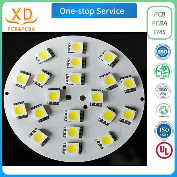
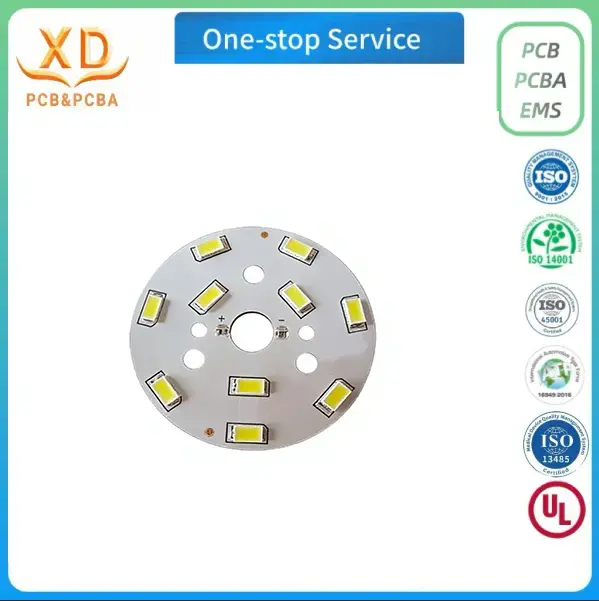
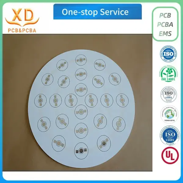
Circular boards are often used where the PCB needs to follow the shape of a lamp housing. Even so, a round outline should not be treated as a simple diameter specification. The board may also require screw holes, slots, notches or clearances for wires and connectors.
When confirming the outline, check the following details:
● Outside diameter: Confirm the available space in the fixture and allow for the actual mounting arrangement.
● Mounting holes: Provide hole sizes, positions and tolerances where required.
● Cutouts and notches: Show features needed to clear housing ribs, wires or other parts.
● Component clearance: Leave room for LEDs and other components without interfering with fasteners or surrounding structures.
● Assembly access: Consider whether the board can be installed and secured using the intended assembly method.
A board that fits on a drawing may still be awkward to assemble if a screw head overlaps a component or if a connector sits too close to the edge. Reviewing the PCB together with the housing drawing can help catch these conflicts before manufacturing.
The outline should also be consistent across the design files. If the mechanical drawing shows one diameter but the fabrication data defines another, the supplier needs clarification before production. A clear, approved outline reduces the risk of receiving boards that match one file but not the intended fixture.
Match Board Thickness to the Available Space
Board thickness affects both the physical fit and the construction of the PCB. For a circular LED aluminum PCB, the selected thickness needs to fit within the lighting fixture while meeting the design's mechanical requirements.
Xinda PCB lists a finished board thickness of 1.0–2.5 mm for its featured custom circular LED aluminum PCB. Its broader aluminum PCB process specification covers finished board thicknesses from 0.4 mm to 3.0 mm. These figures describe different scopes: the first is the stated range for the featured product, while the second is the general process range.
The final specification should be confirmed against the actual design. A thicker board may affect the available height for components, mounting hardware or the contact surface inside the fixture. A thinner board may be unsuitable if the mechanical arrangement calls for a different level of rigidity or a particular mounting interface. The best choice depends on the whole assembly, not on thickness in isolation.
When requesting a quotation, specify the required finished thickness rather than simply asking for an aluminum PCB. If the design allows alternatives, identify the acceptable range and ask the supplier to confirm feasibility. This is more useful than leaving the manufacturer to make an assumption.
Select Copper Thickness Around the Circuit Requirements
Copper thickness is another specification that should follow the electrical design. Xinda PCB lists 1–2 oz copper thickness for the featured circular LED aluminum PCB, while the general aluminum PCB process range is 1–6 oz, depending on the construction and design.
Copper weight should be reviewed together with current requirements, trace width, spacing and the amount of routing space available. A heavier copper specification does not automatically make every circuit better, and it should not be selected without considering the layout and manufacturing requirements.
The design files need to communicate the intended circuit pattern clearly. If the circuit has narrow traces or closely spaced features, those areas should be checked against the manufacturer's stated process capability. Xinda PCB's general process specification lists a minimum trace width and line spacing of 0.15 mm. The feasibility of a specific design still depends on the complete board construction and the data supplied for production.
For a new design, it is sensible to have the supplier review the manufacturing files before the order is released. This gives both sides a chance to identify unclear specifications or potential fabrication concerns while changes are still manageable.
Understand the Role of the Aluminum Base
Aluminum is widely used in LED lighting PCBs because the metal base can help move heat away from the circuit area. In a circular board, the base material is only one part of the overall design. The dielectric layer, copper pattern, LED placement and contact between the PCB and the fixture all influence the result.
The featured Xinda PCB product uses 5052 aluminum alloy. This is the material stated for the product and should be specified when it matches the project's requirements. If a project calls for a different material or construction, that requirement needs to be discussed separately rather than assumed to be covered by the featured product.
The board's installation also matters. A PCB mounted against a suitable heat-transfer surface may behave differently from one with limited contact or an uneven interface. Designers should therefore review the board and its mounting arrangement as parts of the same assembly.
For this reason, material selection should not be used as a substitute for checking the completed lighting design. If operating temperature is important to the application, validation should reflect the actual fixture and operating conditions. The PCB supplier can confirm construction details, while the lighting product team needs to evaluate the complete system.
Plan the LED Layout Around the Optical and Mechanical Design
The LED arrangement affects more than the appearance of the circuit. Component positions must work with the optical design, available board area and mechanical features of the fixture. On a circular PCB, the layout may follow a ring, use several groups of LEDs or adopt another arrangement based on the product's lighting requirements.
The PCB layout should leave sufficient space for mounting holes and other features. It should also account for component dimensions and placement tolerances. If LEDs are positioned too close to a cutout or edge, the design may become difficult to assemble or may conflict with nearby parts.
For panel lights, the board arrangement needs to be considered alongside the diffuser or light guide used by the fixture. For downlights, the relationship between the LED positions, reflector and housing may affect the finished light distribution. These are product-level considerations, so the PCB layout should be reviewed with the relevant mechanical and optical information available.
If the design uses connectors, wires or additional electronic components, their locations should be included in the assembly drawing. This helps the manufacturer understand the intended configuration and makes it easier to identify potential conflicts before samples are produced.
The layout should also leave room for practical assembly work. Components need to be placed where the intended mounting and wiring arrangements can accommodate them. When the board has a tight circular outline, even a small change in component position can affect the space available for a screw, connector or edge clearance. A layout review with the mechanical drawing can help identify these issues before they lead to a revised board.
Check Tolerances and Fit Before Finalizing the Design
Nominal dimensions describe the intended board size, but production drawings also need to address how much variation is acceptable. This matters when a circular PCB must fit inside a molded housing or align with pre-existing mounting points.
Not every dimension needs the same tolerance. A small variation in an area with generous clearance may have little effect on assembly, while a hole that must align with a fixed post can be much more critical. Identify the dimensions that directly affect fit and provide the required tolerances where they matter.
It is also worth reviewing the relationship between the PCB and the parts around it. Consider the space needed for fasteners, wiring and component bodies, as well as any restrictions imposed by the reflector or cover. If the board is intended to contact another surface, check that the mechanical drawing communicates the required interface.
Before approving the design, compare the PCB outline against the latest housing drawing. If the housing is still being revised, make sure the PCB and mechanical teams are working from compatible versions. This simple coordination step can prevent a board from being manufactured to a dimension that is no longer valid.
Confirm the Surface Finish Before Ordering
Surface finish is part of the manufacturing specification and should be selected with the board design and assembly process in mind. Xinda PCB's general aluminum PCB process options include OSP, HASL, immersion gold, lead-free immersion tin and immersion silver.
These finishes should not be treated as interchangeable choices for every project. The appropriate option depends on the design, component assembly requirements and the customer's acceptance criteria. If the PCB will be assembled with electronic components, the selected finish should be confirmed as suitable for the intended assembly process.
The quotation request should name the required finish or ask the manufacturer to review the options against the application. Leaving the finish unspecified may lead to different assumptions between suppliers, making quotations harder to compare.
If a project has an existing approved design, keep the surface finish consistent with that specification unless a change has been reviewed and accepted. This is particularly useful when moving from prototype samples to repeat production.
Which Manufacturing Information Should You Send?
A supplier can assess a custom circular LED aluminum PCB more accurately when the inquiry includes both electrical and mechanical information. A product photograph may help explain the intended use, but it does not provide enough detail for manufacturing on its own.
A practical design package normally includes:
Information | What it should clarify |
Fabrication files | The copper pattern and other manufacturing layers |
Mechanical drawing | Outside diameter, holes, cutouts and critical dimensions |
Material specification | Required aluminum alloy or approved construction |
Finished board thickness | The required thickness and any tolerance |
Copper thickness | The intended copper weight or construction |
Surface finish | The finish required for the design |
Quantity | Sample quantity and expected production volume |
Application details | Fixture type and relevant mounting constraints |
If the order includes component assembly, provide the bill of materials, placement data and assembly drawing as well. These documents help distinguish a bare PCB order from a request for an assembled circuit board.
Revision control is important when files are updated during development. Identify the current version clearly and ensure that the drawing and fabrication data describe the same design. If any dimensions or requirements are still under review, state that before requesting a production quotation.
Check General Process Limits Against the Actual Design
A published process specification helps buyers understand the range a manufacturer may support, but it should not be read as a guarantee that every combination of dimensions, materials and circuit features can be produced without review.
Xinda PCB's general aluminum PCB specification lists a maximum processing size of 120 cm × 60 cm, copper thickness of 1–6 oz, finished board thickness of 0.4–3.0 mm and a minimum trace width and line spacing of 0.15 mm. The featured circular LED aluminum PCB has a more specific stated range of 1.0–2.5 mm finished thickness and 1–2 oz copper thickness.
When a design uses a combination of tight spacing, unusual cutouts, specific thicknesses or other constraints, send the actual manufacturing files for review. The supplier can then confirm whether the requested construction fits the intended process and identify any points that need clarification.
This review is particularly useful for custom shapes. A circular outline may be straightforward, but the combination of holes, notches, trace routing and component positions can make one design different from another. Confirming feasibility before production helps avoid unnecessary changes after samples have been made.
Review Electrical Requirements Alongside the Mechanical Design
Mechanical fit is only one part of a successful PCB selection. The circuit also needs to match the electrical requirements established by the lighting product design. Current demand, trace geometry and the component arrangement should be considered together rather than treated as separate decisions.
The PCB manufacturer needs accurate fabrication data to produce the intended circuit pattern. The product team should ensure that the files reflect the approved design and that any special requirements have been documented. If the circuit is being revised, the latest files should replace outdated versions before the order is released.
Testing should be discussed in terms of the characteristics that need to be checked. Electrical testing may cover continuity and isolation according to the agreed test method, while visual inspection addresses visible features of the manufactured circuit. Neither should be assumed to verify the performance of the complete LED fixture.
For a new lighting design, the product team should establish what needs to be validated at PCB level and what must be checked after installation in the lamp. This distinction helps avoid relying on a board inspection to answer questions that can only be evaluated in the assembled product.
Avoid Common Problems During PCB Selection
Many avoidable problems arise because a requirement was assumed rather than confirmed. A few checks during design review can make the ordering process more predictable.
Choosing the board by diameter alone. The outside diameter may be correct, but mounting holes, cutouts or component clearances may still conflict with the fixture. Review the full outline and assembly drawing before releasing the design.
Using a general specification instead of the required construction. A supplier's broad process range does not automatically define the construction of a particular product. State the required aluminum alloy, finished thickness, copper thickness and surface finish in the inquiry.
Leaving critical tolerances undefined. If a dimension determines whether the board fits or aligns with another part, provide the necessary tolerance. Avoid applying unnecessarily tight tolerances to every feature when only some dimensions affect assembly.
Sending inconsistent manufacturing files. A drawing and fabrication package that describe different versions can lead to delays or incorrect production. Confirm the current revision and resolve discrepancies before ordering.
Assuming all suppliers quote the same scope. One quotation may cover bare-board fabrication, while another includes additional services. Confirm the deliverables, inspection requirements and any assembly work before comparing prices.
These checks do not replace engineering review, but they help make the requirements clearer for both the customer and manufacturer.
Review a Prototype Before Releasing the Production Order
Prototype samples give the lighting team an opportunity to confirm the mechanical fit and compare the manufactured board with the approved design. The review should cover more than whether the PCB looks correct.
Check that the board fits the housing, mounting holes align and components have the required clearance. Verify the material and thickness against the agreed specification. If electrical or functional checks are required, confirm that the relevant tests have been completed and reviewed.
Any requested change should be recorded in the design files before the production order is released. A revised outline, relocated hole or changed copper pattern needs to be reflected in the approved manufacturing package. Otherwise, the supplier may produce the next batch using an earlier version.
Once a sample is approved, retain the corresponding files and specification as the production reference. This makes repeat orders easier to manage and gives both the buyer and supplier a shared basis for checking future deliveries.
Choosing a Supplier for Custom Circular LED Aluminum PCBs
Supplier selection should consider more than the quoted unit price. Buyers need to know whether the manufacturer can support the required board construction, review the supplied files and explain the scope of its inspection process.
Before placing an order, confirm the material, finished thickness, copper specification, surface finish and dimensional requirements in writing. Ask which inspection steps are included and what acceptance criteria will be used. If samples are needed, clarify the sample quantity, approval process and how approved changes will be carried into production.
Xinda PCB offers custom aluminum PCB manufacturing for LED lighting applications, including circular aluminum boards for downlights and panel lights. Its featured product uses 5052 aluminum alloy, with a stated finished board thickness of 1.0–2.5 mm and copper thickness of 1–2 oz. Custom samples and volume orders are accepted.
For a quotation, provide the required board dimensions, fabrication files, material and copper specifications, surface finish and quantity. If the design has special mounting or assembly requirements, include the relevant drawing and explain which dimensions are critical.
Product information is available at www.xdpcba.com. Project inquiries can be sent to bluesky@xdpcba.com or Sales10@xdpcba.com.
A Clear Specification Makes Custom PCB Ordering Easier
Choosing a circular LED aluminum PCB is a design decision that connects the lighting fixture to the manufacturing process. The board outline must fit the housing, the thickness and copper construction must match the requirements, and the files need to communicate the intended design without ambiguity.
A complete specification gives the supplier a sound basis for quotation and helps the product team review samples against the actual requirements. When the design, manufacturing data and acceptance criteria are aligned, it becomes easier to move from an initial prototype to repeat orders with fewer avoidable revisions.
For downlight and panel light projects, start with the fixture dimensions and mounting arrangement, confirm the board construction, and have the manufacturing files reviewed before production. These steps help keep the PCB selection practical and the ordering process clear.
Label: