PCB Process
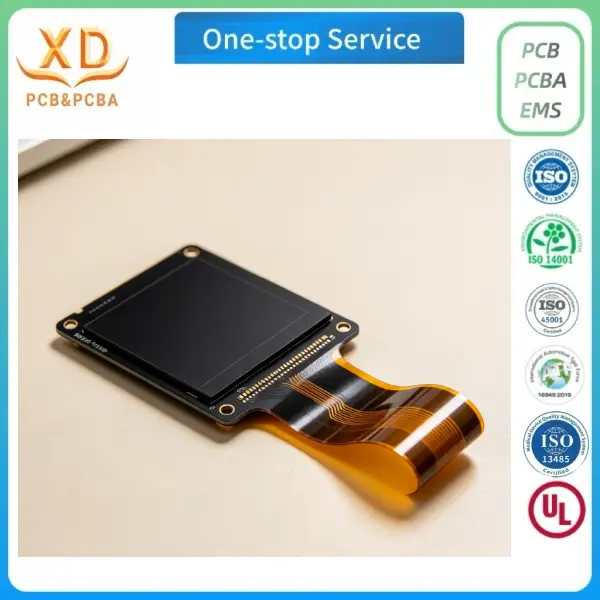
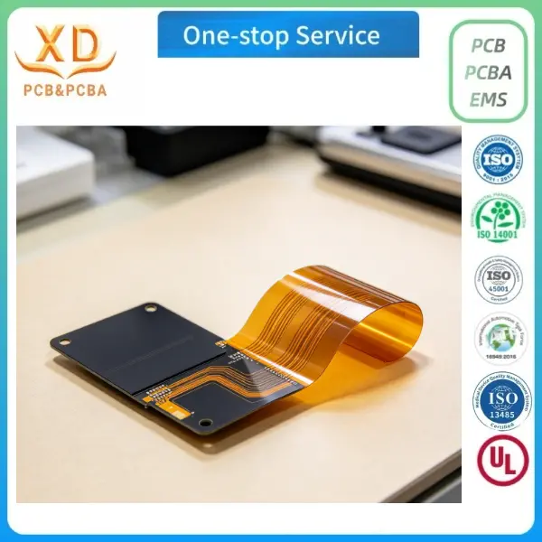
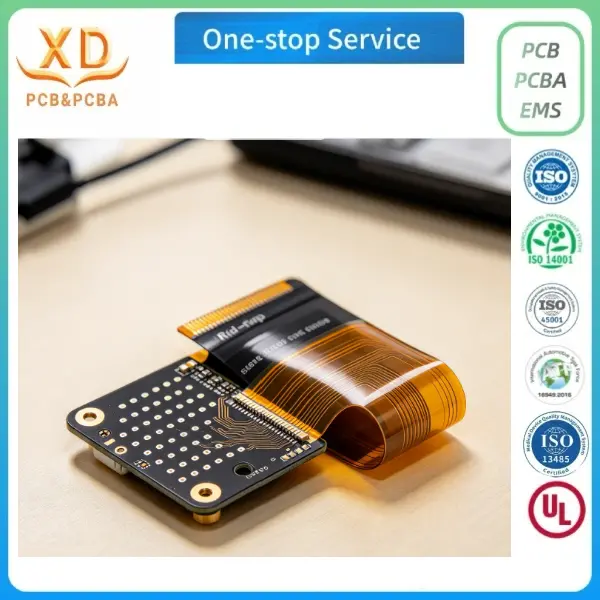
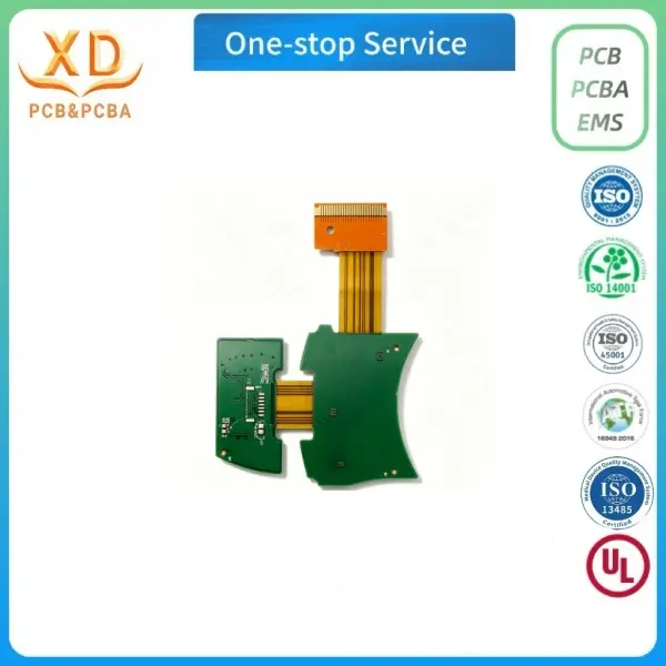
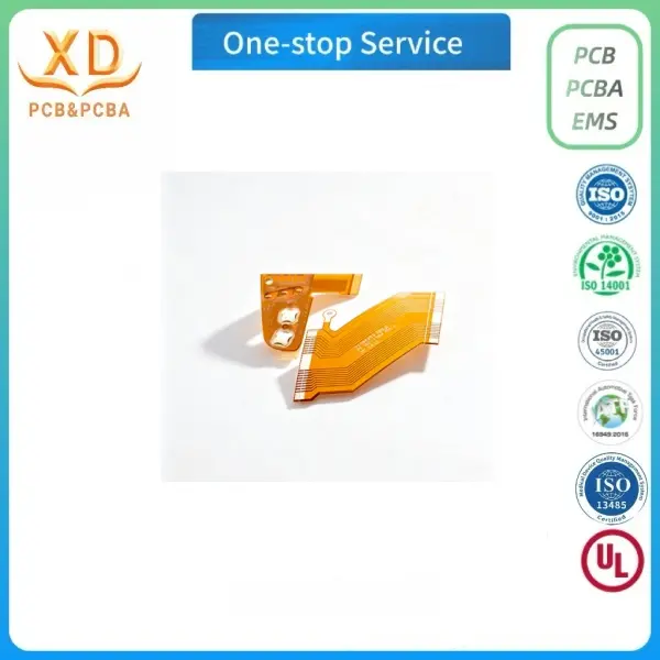
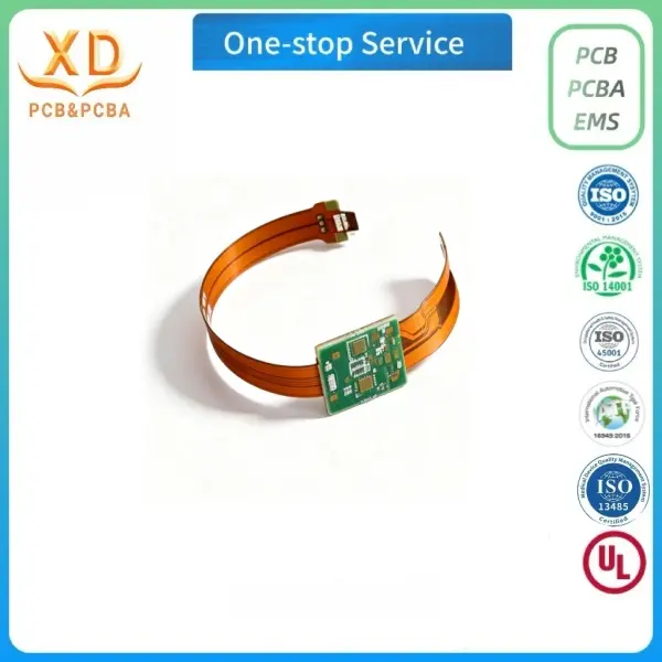
1. Layer count: 4 layers, rigid-flex hybrid structure
2.Base material: Polyimide (PI) for flexible section, FR4 for rigid section
3.Base copper thickness: 18μm /18μm for both rigid & flex area
4.Board thickness: 0.45~0.55mm, flex part ~0.18±0.03mm, stiffener ~0.23±0.03mm
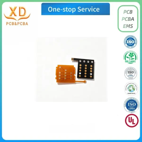
5.Coverlay: Yellow coverlay, top & bottom side
6.Solder mask: Green solder mask on top and bottom
7.Silkscreen: White silkscreen, top & bottom
8.Surface finish: ENIG (Immersion Gold)
9.Via process: Plugged holes available, hole size 0.11×0.3mm
10.Minimum line width/spacing: 0.04mm / 0.04mm
11.Electrical test: Flying probe test required
12.Outline routing: CNC routing, tolerance ±0.1mm
13.Capability: Support blind & buried vias, coverlay thickness 27~50μm, adhesive 12~25μm
14.Panel: 6 pcs per panel
15.Other: Extra copper on panel for PCB reinforcement, V-Cut not required
PCB Application Scenarios
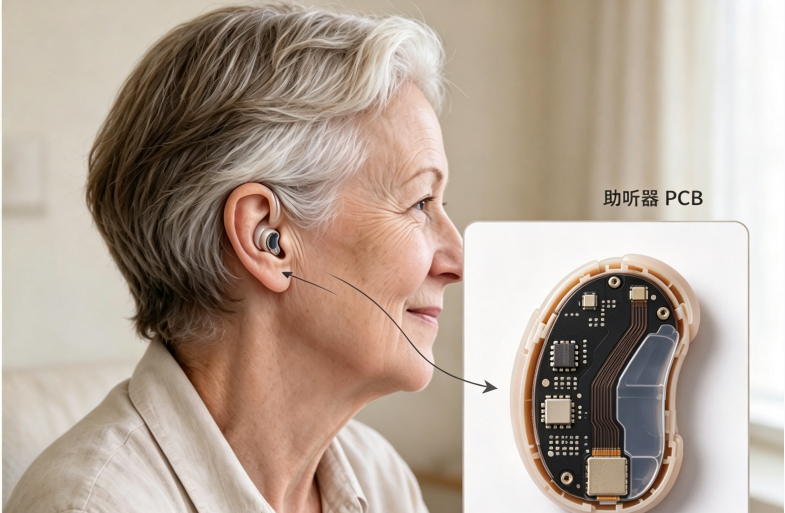
This rigid-flex FPC is designed for hearing aid devices.
It fits into tiny, curved housing of in-ear hearing aids, receiver-in-canal hearing aids,
Bluetooth hearing aids and audiology accessories.
The flexible segment can bend freely inside ear shells, while rigid zones carry microphones,
DSP chips and power management components.
Stable signal transmission, anti-fatigue bending
and medical-grade reliability meet the long-term use requirement of hearing aid products.
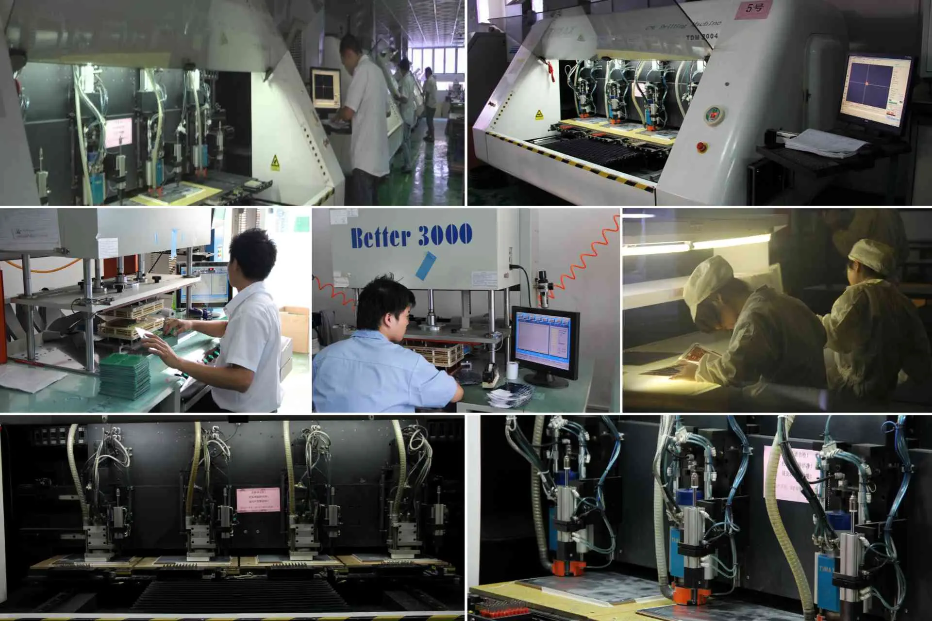
PCB Production Line
Our PCB workshop carries out rigid-flex board fabrication including PI lamination,
coverlay bonding, drilling, plating, ENIG surface finishing, routing and flying probe testing.
Carbon fiber stiffener (carbon plate) is precisely laminated onto designated FPC reinforcement
area under controlled temperature and pressure, to enhance local rigidity for component
soldering while keeping other sections flexible.
Every hearing aid PCB is strictly inspected before shipment.
Contact Us
Contact us for any help regarding Hearing aids Multilayer rigid flex pcb:
Website: www.xdpcba.com
Email: sales10@xdpcba.com sales@xdpcba.com

 0755-27781532-8010; 02988446863