0755-27781532-8010; 02988446863















Nov 09, 2026
Flexible PCB vs. Rigid-Flex PCB: Key Design Differences
Nov 09
Intelligent Browse: 0
Compact electronic products often place strict demands on the circuit board. Limited internal space, irregular housing structures, moving components, and dense electrical connections can make a conventional rigid PCB difficult to integrate. Flexible PCB and rigid-flex PCB technologies provide two different approaches to these design challenges, but they are not interchangeable in every application.
A flexible PCB is built around a flexible substrate that allows the circuit to bend, fold, or conform to the available installation space. A rigid-flex PCB combines rigid board sections with flexible circuit sections in one interconnected structure. The choice between them depends on the mechanical structure, connection requirements, bending conditions, component placement, assembly method, and production objectives of the electronic product.
For OEM and product development teams, the important question is not simply which technology is more flexible. The more useful question is which PCB structure provides the right combination of electrical performance, mechanical integration, assembly efficiency, and long-term reliability.
For more information on flexible circuit and rigid-flex board manufacturing, the FPC and Rigid-Flex PCB solutions available from Xing Da provide a useful reference for different board structures and applications.
What Is a Flexible PCB?
A flexible PCB, also called an FPC or flexible circuit board, uses a flexible base material to create an electrical circuit that can conform to a product's internal structure. Polyimide is a common substrate material for flexible circuits, while other materials can be selected according to the electrical, thermal, mechanical, and manufacturing requirements of a particular design.
The main characteristic of a flexible PCB is mechanical flexibility. Instead of occupying a flat, fixed position like a conventional rigid board, an FPC can be routed through narrow spaces, folded around components, or positioned along curved product housings.
This makes flexible PCBs useful in products where internal space is limited or where a cable and circuit board need to be combined into a single component.
Typical applications include:
Wearable electronic devices
Compact consumer electronics
Thermal printers
Display and touch interfaces
Cameras and sensors
Medical wearable devices
Small communication modules
Space-constrained electronic assemblies
The flexibility of an FPC does not mean that every flexible circuit is designed for continuous movement. A board intended for static folding during assembly has different mechanical requirements from an FPC used in a repeated bending application. Bend radius, copper structure, coverlay design, routing, and mechanical support all need to be considered during PCB design.
What Is a Rigid-Flex PCB?
A rigid-flex PCB combines rigid PCB sections and flexible circuit sections within a single board structure. The rigid portions provide stable areas for component mounting, connectors, or mechanical support, while the flexible sections allow the circuit to pass between different parts of the product.
This structure is particularly useful when an electronic assembly contains several separate rigid circuit areas that would otherwise need cables, connectors, or multiple boards to communicate with each other.
A rigid-flex design can therefore reduce the need for additional interconnection components. The flexible section acts as an integrated electrical bridge between rigid sections.
Common application areas include:
Wearable electronics
Smart devices
Medical electronics
Compact communication equipment
Industrial control devices
Sensors and measurement equipment
Automotive electronic modules
Devices with folded or three-dimensional internal structures
The key point is that rigid-flex PCB technology combines two different mechanical characteristics in one circuit structure. The rigid areas can support components, while the flexible areas accommodate routing and mechanical movement or folding.
This makes rigid-flex particularly attractive when a product needs both reliable component mounting and three-dimensional circuit integration.
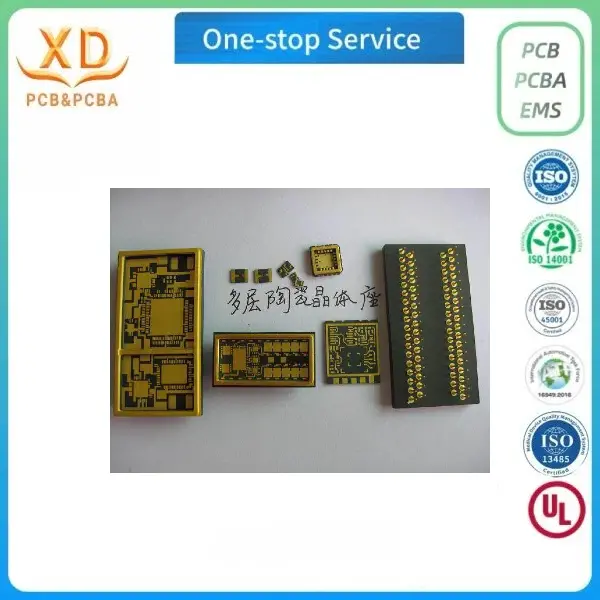
Flexible PCB vs. Rigid-Flex PCB: Main Differences
The fundamental difference lies in the board structure.
| Factor | Flexible PCB | Rigid-Flex PCB |
|---|---|---|
| Basic structure | Flexible circuit throughout | Rigid sections connected by flexible sections |
| Main advantage | Bending and space-saving routing | Combination of component support and flexibility |
| Component mounting | Possible, depending on design | Rigid sections are generally better suited for component mounting |
| Mechanical integration | High flexibility | High integration across multiple rigid areas |
| Connection method | May require connectors or other interfaces | Flexible sections can integrate connections between rigid areas |
| Typical use | Compact and flexible circuits | Complex three-dimensional assemblies |
| Design complexity | Depends on layer count and mechanical requirements | Generally higher due to mixed rigid/flexible construction |
| Cost considerations | Often suitable for cable-replacement applications | Can require more complex fabrication and assembly |
| Best fit | Flexible routing and space-constrained circuits | Multi-board structures that need integrated flexibility |
Neither technology is automatically the better choice. The appropriate solution depends on the product architecture.
A simple flexible interconnect may not require rigid-flex construction. Conversely, a product with several component-bearing circuit sections may become unnecessarily complicated if designers attempt to use a fully flexible circuit for every function.
Mechanical Structure and Space Requirements
Mechanical structure is one of the most important factors when selecting between flexible PCB and rigid-flex PCB technology.
A flexible PCB is well suited to products where the circuit needs to follow a curved surface, pass through a narrow opening, or fold into a compact area. For example, an FPC can replace a separate cable assembly between two electronic modules while occupying less installation space.
Rigid-flex becomes more useful when the product contains multiple rigid areas that need to be electrically connected while following a three-dimensional mechanical structure.
Consider a compact device with a main control board, a sensor board, and a display board. A conventional design might use three rigid PCBs connected with cables or connectors. A rigid-flex structure can potentially integrate these sections into one board assembly, with flexible sections positioned between the rigid areas.
The decision should therefore begin with the mechanical layout rather than the PCB material alone.
Design teams should examine:
Available installation space
Product folding or bending requirements
Component locations
Connector locations
Cable routing
Housing geometry
Required bend radius
Assembly sequence
Potential mechanical stress points
A board that fits the electrical schematic but cannot be assembled into the product housing is not a successful PCB design.
Electrical Routing and Signal Integrity
Electrical requirements also influence the choice between flexible PCB and rigid-flex PCB.
Flexible circuits can support dense routing in compact areas, but the electrical design must account for the mechanical behavior of the flexible section. Trace placement, bend direction, bend radius, copper geometry, layer structure, and impedance requirements can all affect the final design.
Rigid-flex PCBs add another consideration because the design transitions between rigid and flexible regions.
The transition area needs careful attention. Poorly designed transitions can create mechanical stress concentrations or make fabrication more difficult. Trace routing should also account for the expected bending area and avoid placing sensitive features where repeated mechanical movement could create reliability concerns.
For high-speed or high-frequency applications, electrical requirements should be considered together with the mechanical design. Controlled impedance, layer stackup, trace geometry, grounding, and signal routing remain important regardless of whether the circuit is flexible or rigid-flex.
The choice of PCB structure should therefore be made at the system design stage rather than after the electrical layout has already been completed.
Component Mounting and Assembly Considerations
Component mounting is another major difference.
A flexible PCB can support electronic components, but its mechanical flexibility may limit where and how components should be placed. Areas that experience repeated bending generally need to be separated from component-heavy regions.
Rigid-flex PCB designs provide dedicated rigid areas that are better suited to component mounting. This can make the technology more practical for assemblies that combine dense electronic components with flexible interconnections.
For example, a wearable device may require sensors, processors, wireless components, and power-management components in a small area while also needing the circuit to follow the shape of the housing. A rigid-flex design can place components on rigid sections while using flexible sections for internal routing.
Assembly planning should include:
Component placement
Components should be positioned according to the mechanical and electrical requirements of each board section. Flexible zones should not be treated as ordinary rigid PCB areas.
Soldering requirements
The assembly process needs to match the materials and construction of the board. Flexible sections may require additional handling controls during SMT assembly.
Stiffener requirements
Some FPC designs use stiffeners in connector or component areas to provide additional mechanical support. The need for a stiffener depends on the specific board design and connection method.
Inspection and testing
Electrical testing, visual inspection, and other applicable inspection methods should be planned according to the board structure and product requirements.
These considerations can affect the total manufacturing cost, so PCB selection should include assembly planning rather than focusing only on fabrication cost.
Bendability and Mechanical Reliability
Flexibility is one of the main reasons engineers choose an FPC or rigid-flex PCB, but the term “flexible” does not describe a single mechanical condition.
There are several different bending scenarios.
Static bending occurs when the circuit is bent into a particular position during product assembly and remains there during normal operation.
Dynamic bending occurs when the circuit repeatedly bends during product use.
Folding involves a defined folding operation that places the flexible section into a compact product structure.
Each condition creates different mechanical requirements.
Copper type, copper thickness, trace geometry, substrate construction, coverlay, bend radius, layer count, and bending direction can all influence mechanical performance.
A design intended for repeated bending therefore requires more careful mechanical analysis than a circuit that is simply folded once during assembly.
Rigid-flex PCBs also require attention to the transition between rigid and flexible sections. These areas can experience mechanical stress during assembly or operation and should be designed according to the intended movement and installation conditions.
Which Applications Suit Flexible PCB Better?
Flexible PCB is generally a strong candidate when the primary requirement is flexible routing rather than a large number of rigid component-mounting areas.
Typical situations include:
Cable replacement
An FPC can combine electrical connections and flexible routing into one circuit structure, potentially reducing the need for separate cable assemblies and connectors.
Thin electronic products
Where product thickness is tightly controlled, a flexible circuit can provide a compact routing solution.
Curved housings
FPCs can follow certain curved product structures more easily than conventional rigid boards.
Moving interfaces
When a circuit needs to accommodate controlled mechanical movement, a flexible PCB can be considered if the bending requirements are properly defined.
Compact modules
Small sensors, displays, printers, and wearable electronics may benefit from flexible routing where internal space is limited.
The key requirement is a clear mechanical definition. The expected bend radius, movement frequency, installation method, and operating environment should be established before the PCB layout is finalized.
Which Applications Suit Rigid-Flex PCB Better?
Rigid-flex PCB is generally more suitable when the electronic product needs both stable component-mounting areas and flexible interconnections.
It can be considered for:
Wearable devices with multiple electronic sections
Compact medical electronics
Small wireless devices
Folded electronic assemblies
Products with limited internal connectors
Multi-board structures requiring integrated connections
Three-dimensional electronic assemblies
A rigid-flex structure can simplify the physical architecture when several rigid PCB sections need to communicate across a constrained mechanical structure.
However, rigid-flex should not be selected simply because it is more advanced. If a standard flexible circuit can meet the mechanical and electrical requirements, a simpler solution may be more appropriate.
Cost and Manufacturing Considerations
PCB cost depends on much more than substrate material.
For flexible PCB and rigid-flex PCB projects, manufacturers may evaluate:
Layer count
Board dimensions
Material selection
Copper thickness
Circuit density
Minimum trace and spacing requirements
Via structure
Surface finish
Coverlay or solder mask
Stiffeners
Special mechanical requirements
Production volume
Testing requirements
Assembly requirements
Rigid-flex designs can involve additional fabrication steps because rigid and flexible sections are integrated into the same board structure. This can make the manufacturing process more complex than a straightforward flexible circuit.
At the same time, the overall product cost should not be judged only by the PCB unit price.
A rigid-flex PCB may replace multiple rigid boards, cables, and connectors. In a suitable product architecture, reducing the number of separate interconnections can simplify assembly and improve space utilization.
For this reason, OEM buyers should compare the total assembly structure, rather than comparing only the quotation for one PCB.
How to Select a Flexible PCB or Rigid-Flex PCB Manufacturer
Supplier selection should begin with technical capability rather than price alone.
A suitable manufacturer should be able to review the board structure against the intended application and identify manufacturing risks before production.
Important areas to evaluate include:
Flexible PCB manufacturing capability
For FPC projects, ask about the manufacturer's experience with flexible substrates, coverlay processing, stiffeners, fine-line circuits, multilayer structures, and electrical testing.
Rigid-flex manufacturing capability
For rigid-flex projects, review the manufacturer's experience with rigid-to-flex transition structures, multilayer rigid-flex boards, material combinations, and the specific mechanical requirements of the application.
Design review
A capable supplier should be able to identify manufacturability concerns from the design files rather than waiting until production problems occur.
Prototype and volume production
OEM projects often move from prototype quantities to larger production volumes. Supplier evaluation should therefore consider whether the manufacturing process can support the expected production stage.
Testing and quality control
The appropriate electrical and manufacturing tests depend on the board design and application. Testing requirements should be defined during the engineering stage.
Communication and engineering support
For custom flexible PCB projects, communication between the product designer and PCB manufacturer is important because mechanical and electrical requirements are closely connected.
Xing Da's current FPC product information lists flexible PCB and rigid-flex PCB manufacturing among its offerings, with product examples covering printer FPC, wearable-related circuits, smart devices, and other compact electronic applications.
A Practical Selection Guide for OEM Projects
The following decision framework can help product teams narrow down the appropriate PCB structure.
| Project Requirement | Recommended Direction |
|---|---|
| Flexible routing with limited component mounting | Flexible PCB |
| Cable replacement | Flexible PCB |
| Thin or curved internal routing | Flexible PCB |
| Multiple rigid component areas | Rigid-Flex PCB |
| Several PCB sections connected in a compact structure | Rigid-Flex PCB |
| Three-dimensional circuit integration | Rigid-Flex PCB |
| Repeated bending | FPC or rigid-flex, depending on mechanical design |
| Simple flexible interconnection | Flexible PCB |
| Complex compact assembly with rigid and flexible zones | Rigid-Flex PCB |
This table is only a starting point. The final selection should be based on the actual product structure, electrical requirements, bending conditions, assembly process, and production requirements.
Flexible PCB vs. Rigid-Flex PCB: Which One Should You Choose?
Flexible PCB and rigid-flex PCB solve related but different engineering problems.
A flexible PCB is often the more direct solution when the circuit primarily needs flexible routing, thin construction, or controlled bending. It can be particularly effective as a cable replacement or in compact products where a conventional rigid board cannot follow the available installation path.
A rigid-flex PCB becomes more attractive when the product requires several rigid component-mounting areas connected through flexible sections. It can support more complex three-dimensional electronic structures and may reduce the number of separate boards, cables, and connectors required in the assembly.
The most reliable selection process starts with the product architecture. Mechanical space, bending conditions, component placement, signal requirements, assembly method, testing, production volume, and total system cost should all be considered before the PCB structure is finalized.
For OEM projects that require a custom flexible PCB or rigid-flex PCB, early communication with the manufacturer can also help identify design and manufacturing constraints before tooling or mass production begins. For project consultation, technical requirements, or custom PCB manufacturing inquiries, Contact Us with the required board information and application details.
Label: