0755-27781532-8010; 02988446863














Oct 10, 2026
Long Strip Aluminum Circuit Board for Linear Lights and LED Tube Lights
Nov 02
Intelligent Browse: 0
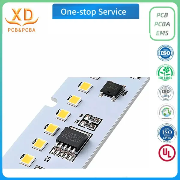
Linear lighting products require circuit boards that fit narrow spaces, support the required LED arrangement, and provide a suitable path for heat transfer. Whether used in commercial linear lights, LED tube lights, or cabinet lighting, the PCB must match the fixture's length, width, mounting structure, and electrical design. A well-designed pcb board led solution helps connect SMD LEDs and supporting components while keeping the overall lighting assembly practical to manufacture and install.
For lighting manufacturers, a long strip aluminum circuit board offers a metal-core structure for applications where heat dissipation is an important consideration. Its elongated shape can be customized to fit different lamp housings, while the circuit layout can be arranged according to LED quantity, spacing, power requirements, and connection positions.
Xing Da provides customized aluminum PCB fabrication and PCBA assembly services for linear lighting projects. Available services include PCB layout design, aluminum substrate fabrication, SMD LED soldering, BOM component sourcing, and aging tests. Both bare boards and assembled boards can be discussed according to project requirements.
Long Strip Aluminum PCB for Linear Lighting Applications
Linear lights use an elongated lighting structure to distribute illumination along a defined area. The PCB is usually designed to follow the shape of the fixture, with LEDs arranged along the board and electrical connections positioned to suit the product's power supply and installation method.
A long strip aluminum PCB can be considered for several types of lighting products.
LED Linear Lights
LED linear lights are used in offices, retail stores, commercial buildings, corridors, and other indoor spaces. Their housings may be designed for suspended, surface-mounted, or recessed installation.
The PCB needs to match the available internal space and the intended LED arrangement. Board length, width, component height, and connector position should be confirmed before fabrication.
For longer fixtures, the electrical layout should also account for power distribution along the board. The design should consider the current required by the LED groups and the voltage drop across the conductive paths.
LED Tube Lights
LED tube lights are commonly used in offices, workshops, warehouses, commercial buildings, and residential spaces. Their internal structure often requires a narrow PCB that fits inside a tubular housing.
A custom pcb led board can be designed around the tube's internal dimensions, LED package, power circuit, and end-connection structure.
Important design details include:
PCB width and overall length
LED package and spacing
Input power connection
Driver component arrangement
Mounting and fixing positions
Clearance between components and the housing
The final board dimensions should be checked against the actual tube structure to prevent interference during assembly.
Cabinet and Display Lighting
Cabinet lights are installed in furniture, display cabinets, retail shelving, kitchens, and storage areas. These products often use narrow lighting fixtures that need to fit into limited spaces.
A long strip PCB can support an evenly arranged LED layout along the fixture. The board outline, mounting holes, connector positions, and component height should follow the mechanical design of the cabinet lighting assembly.
Commercial and Industrial Lighting
Long aluminum PCBs may also be considered for linear lighting used in commercial and industrial environments. Examples include warehouse lighting, high-bay fixtures, workbench lighting, and other elongated LED luminaires.
The material and circuit design should be selected according to the electrical load, operating temperature, fixture structure, and installation environment.
Aluminum Circuit Board Structure and Material Selection
An aluminum circuit board, also known as an aluminum-based metal-core PCB (MCPCB), uses a metal base to support heat transfer from the circuit area.
A typical aluminum PCB consists of three main layers.
| Layer | Function |
|---|---|
| Copper circuit layer | Forms the conductive paths and component connection pads |
| Dielectric insulation layer | Separates the copper circuit from the aluminum base while providing a thermal path |
| Aluminum base | Provides mechanical support and helps transfer heat away from the circuit area |
This structure is commonly considered for LED lighting products because LEDs generate heat during operation. The aluminum base helps move heat toward the board's mounting surface or connected heat-dissipation structure.
Why Aluminum Is Used for LED Lighting PCBs
Heat transfer
The metal base provides a route for heat to move away from the circuit area. Its effectiveness depends on the dielectric layer, board structure, mounting conditions, and the thermal design of the complete fixture.
Mechanical support
The aluminum base provides a rigid structure for the circuit layer. This is useful for long boards that need to maintain their shape during assembly and installation.
Suitability for elongated layouts
Aluminum PCBs can be manufactured in long and narrow shapes to match linear lighting housings. Board dimensions and mounting details can be adjusted according to the customer's drawings.
Support for SMD LED assembly
The circuit layer provides pads for SMD LEDs and other electronic components. The board can be supplied as a bare PCB or as an assembled PCBA, depending on the customer's requirements.
Material and Specification Selection
The material and board specifications should be confirmed before production. Relevant details include:
Aluminum substrate grade
Dielectric layer properties
Finished board thickness
Copper thickness
Minimum trace width and spacing
Surface finish
Board dimensions and tolerance
These specifications affect electrical performance, heat transfer, mechanical strength, and manufacturing feasibility. They should be selected according to the LED circuit and fixture design rather than copied from another lighting project.
LED Layout Design for Long Strip PCB Boards
The LED arrangement is one of the main factors affecting the layout of a long strip circuit board. The number of LEDs, package size, spacing, and electrical connection method all influence the available routing space.
LED Quantity and Spacing
The required LED quantity depends on the lighting design, target brightness, fixture length, and selected LED package.
The spacing between LEDs should follow the optical and electrical requirements of the product. Uneven placement may lead to inconsistent light distribution, while an arrangement that is too dense can create additional thermal and assembly challenges.
Before layout begins, the manufacturer should receive the LED part numbers, package dimensions, circuit diagram, and intended board dimensions.
Circuit Routing Along the Board
Long strip boards need conductive paths that connect LED groups and supporting components along the length of the PCB.
The layout should consider:
Current requirements of each LED group
Trace width and copper thickness
Voltage drop along the board
Power input location
Ground return paths
Connection between LED sections
Electrical clearance and spacing
For longer boards, voltage drop may become more noticeable if the circuit and power distribution are not planned properly. Engineers should review the current path and connection arrangement based on the actual circuit.
Component Placement
In addition to LEDs, a linear lighting PCB may contain resistors, capacitors, connectors, MOSFETs, and other components depending on the circuit design.
Component placement should account for the limited width of the board and the internal space of the lamp housing. Components should not interfere with mounting structures, covers, or other mechanical parts.
The placement file and assembly drawing should be consistent with the approved PCB layout.
Thermal Management for Long Strip Aluminum PCB
Thermal management is an important part of LED lighting design. LEDs and supporting electronic components generate heat during operation. If heat accumulates around the components, operating temperature may rise and affect the service life and performance of the lighting assembly.
An aluminum circuit board provides a thermal path through its dielectric layer and metal base. However, the PCB material alone does not determine the thermal performance of the finished product.
LED Power and Heat Distribution
The power consumption and arrangement of LEDs influence how heat is distributed along the board.
A long strip PCB may contain multiple LED groups. Their spacing, current, and position should be reviewed to identify areas where heat may become concentrated.
The design should consider:
Total LED power
Number and spacing of LEDs
Heat generated by driver components
Available aluminum base area
Contact between the PCB and fixture housing
Ventilation and enclosure structure
Dielectric Layer Selection
The dielectric layer electrically separates the copper circuit from the aluminum base. It also forms part of the thermal path.
Its electrical insulation and thermal properties should be suitable for the operating conditions of the lighting product. The appropriate dielectric specification depends on the circuit voltage, thermal requirements, and board construction.
PCB and Lamp Housing Contact
The lamp housing can contribute to heat dissipation when the PCB is installed correctly. The contact surface between the aluminum base and the fixture should be considered during mechanical design.
Mounting conditions, surface flatness, thermal interface materials, and the housing structure may influence heat transfer.
For this reason, thermal evaluation should be carried out on the assembled lighting product under representative operating conditions. Measuring the temperature of the PCB and relevant components can help identify design issues before mass production.
PCB Dimensions and Mechanical Design for Linear Lights
A long strip aluminum PCB must fit the lighting fixture without interfering with other components. Mechanical dimensions should be reviewed before the manufacturing files are finalized.
Board Length and Width
The overall board dimensions should match the available installation space. The required length and width may vary between linear lights, tube lights, and cabinet lighting products.
Customers should provide dimensioned drawings whenever possible. If the design includes multiple board sections, the connection and alignment between sections should also be specified.
Mounting Holes and Fixing Positions
Mounting holes, slots, and fixing points need to match the fixture structure. Incorrect positions may cause installation problems or prevent the board from making proper contact with the intended thermal surface.
Component Height and Clearance
The height of SMD components should be checked against the available space inside the lamp housing. This is particularly important for narrow tube lights, where the internal clearance may be limited.
Connectors, capacitors, and other relatively tall components should be positioned according to the mechanical drawing.
Board Segmentation and Connection
Some lighting designs use more than one PCB section to cover the required fixture length. In these cases, the electrical and mechanical connection between sections should be clearly defined.
The design should specify whether the sections are connected through wires, connectors, solder joints, or another approved method. The connection method should be suitable for the fixture's installation and maintenance requirements.
Long Strip Aluminum PCB Fabrication and PCBA Assembly
Manufacturing a long strip aluminum circuit board involves several stages. The exact process depends on the board design, material, and whether the customer requires a bare PCB or a completed PCBA.
PCB Design and Engineering Review
The design stage converts the circuit and mechanical requirements into manufacturing data.
Customers may provide:
Gerber files
Circuit diagrams
BOM files
Pick-and-place files
Mechanical drawings
LED package specifications
Board thickness and copper requirements
The manufacturing team can review the supplied data for missing information and potential production issues before fabrication.
Aluminum PCB Fabrication
A typical aluminum PCB production process includes the following stages:
Incoming material inspection: Checks the aluminum substrate and copper material against the production requirements.
Cutting: Prepares the material to the required dimensions.
Imaging: Transfers the circuit pattern to the copper surface.
Etching: Removes unwanted copper to form the conductive pattern.
Solder mask printing: Applies the protective solder mask to the designated areas.
AOI inspection: Checks visible circuit pattern defects.
Electrical testing: Checks circuit connectivity and isolation according to the applicable requirements.
Final inspection and packaging: Completes the required checks before shipment.
The finished board should be checked against the approved design and manufacturing specifications.
SMD LED Soldering and SMT Assembly
For customers who require assembled boards, SMD LEDs and other electronic components can be mounted through the SMT process.
A typical assembly workflow includes solder paste printing, component placement, reflow soldering, and inspection.
The solder paste stencil should match the PCB pad design. Component placement should follow the approved pick-and-place data, including LED orientation and component position.
After reflow soldering, the board should be inspected for component alignment, solder joints, missing parts, and other visible assembly issues.
BOM Component Sourcing
A complete BOM helps clarify the electronic components required for assembly. It should include part numbers, specifications, quantities, and approved alternatives where applicable.
Component substitutions should be reviewed before production to avoid differences in electrical characteristics, package dimensions, or assembly compatibility.
Aging Tests and Quality Inspection for LED PCBA
Inspection is necessary at both the bare-board and assembled-board stages. Different methods help identify different types of manufacturing problems.
| Inspection or test | Purpose |
|---|---|
| Visual inspection | Checks the visible condition of the PCB and assembled components |
| AOI | Identifies visible circuit and component placement defects |
| Electrical testing | Checks connectivity and isolation according to the test requirements |
| Power-on testing | Checks the board under the specified power conditions |
| Aging test | Operates the assembled product under defined conditions for a specified period |
| Functional testing | Checks the lighting functions according to the agreed test procedure |
An aging test can help identify certain issues that may appear during continuous operation. Its conditions should be defined according to the product design, including operating time, power conditions, and acceptance criteria.
It is important to distinguish between different inspection methods. AOI checks visible assembly conditions, while electrical and functional tests examine different aspects of board operation. No single inspection method replaces the complete quality plan.
For custom LED lighting projects, customers should confirm the required inspection scope before production. This helps ensure that the manufacturer and customer use the same acceptance criteria.
Information Required for a Custom Long Strip PCB Order
Accurate technical information helps the manufacturer evaluate the design and prepare a suitable production plan.
Before requesting a quotation, customers should prepare the following information where available.
| Information | Why it is needed |
|---|---|
| Gerber files | Defines the PCB circuit pattern |
| BOM | Lists the required components |
| Circuit diagram | Shows the electrical connections |
| Pick-and-place file | Defines component positions and orientations |
| Mechanical drawing | Specifies board length, width, holes, and mounting positions |
| LED specifications | Identifies LED packages and electrical requirements |
| Board material | Confirms the required aluminum substrate |
| Board thickness | Defines the mechanical thickness |
| Copper thickness | Helps determine the circuit's current capacity |
| Surface finish | Specifies the required PCB surface treatment |
| Order quantity | Supports quotation and production planning |
| Testing requirements | Defines inspection and aging test conditions |
If the project is still at the development stage, customers can provide an existing sample, preliminary drawing, or product description for an initial review.
The remaining details can then be clarified before the final manufacturing files are approved.
Choosing a Manufacturer for LED Aluminum Circuit Boards
A suitable PCB manufacturer should be able to review the electrical and mechanical requirements of the lighting product and provide a manufacturing plan that matches the project.
Aluminum PCB fabrication capability
Confirm whether the supplier can produce the required long strip dimensions, substrate structure, copper specifications, and surface finish.
SMD assembly experience
Check whether the supplier can handle the selected LED packages and supporting components. Component placement and soldering requirements should be reviewed before production.
Engineering and layout support
A manufacturer that can review Gerber files, BOM data, and mechanical drawings can help identify missing information before fabrication.
Component sourcing
For PCBA orders, confirm whether the supplier can source the required LEDs, driver components, connectors, and passive components according to the approved BOM.
Inspection and aging test arrangements
Ask which inspection and testing methods are available. The test conditions should be agreed upon according to the lighting product's operating requirements.
Prototype and production orders
Prototype and mass-production orders may have different manufacturing and planning requirements. Confirm the supplier's ability to support the expected quantities and delivery schedule.
Clear communication about specifications, engineering changes, and acceptance criteria helps reduce production misunderstandings.
A reliable pcb board led solution for linear lighting needs to match the fixture's dimensions, LED arrangement, electrical requirements, and thermal conditions. A long strip aluminum circuit board provides a metal-core structure for applications where heat transfer is an important part of the design.
From LED linear lights and tube lights to cabinet lighting and commercial fixtures, the board layout should be developed around the actual product structure. Material selection, copper design, component placement, and assembly requirements should all be reviewed before production.
Xing Da provides customized aluminum PCB fabrication and PCBA assembly services, including PCB layout design, SMD LED soldering, BOM component sourcing, and aging tests. Customers can prepare their Gerber files, BOM, mechanical drawings, and project specifications and contact the Xing Da team to discuss custom long strip aluminum PCB requirements and production arrangements.
Label: